


Wrong cavity count is one of the most costly design errors in injection mold design. If there aren’t enough cavities, throughput is left on the table. Excessive cavities, on the other hand, inflates tooling cost, requires a bigger machine and lengthens mold lead time.
This guide will provide you with the technical framework for designing the correct number of mold cavities.
What Is Mold Cavity Count and Why Does It Matter?

Cavity Count is the number of identical part impressions that are cut in a one base mold. The filling of each impression occurs simultaneously during one injection cycle. If the mold has 1 cavity, there will be 1 part per shot and if the mold has 16 cavities, there will be 16 parts per shot. This multiplier regulates the output rate, per part cost, tooling investment, machine tonnage requirement as well as mold’s lead time.
It’s not just a matter of “the more, the better”. It is a limited optimization problem with three simultaneously-valid inputs:
- The quantity of production you must meet.
- The available machine resources.
- Your overall budget in the entire lifecycle of the product.
Solve them all simultaneously or else you will optimize one at the cost of the other two.
5 Key Factors That Determine Optimal Cavity Count
A proper balance between machine limits and production targets is needed to determine the correct number of cavities. These five factors are the technical limits for a very efficient molding process.
1. Annual Production Volume Requirements
Volume is the main motivator. Your tooling strategy is determined by the annual requirement. Matching the number of cavities with the lifetime-volume will allow for efficient recovery of the mold’s upfront costs. As a general rule:
- < 50,000 parts/year: 1- or 2-cavity tooling. A higher number of cavities will not usually make the tooling cost worthwhile in the short-run.
- 50,000 – 500,000 parts/year: 4- to 8-cavity tooling, depending on part size and machine availability.
- 500,000 parts/year: 8-, 16-, or 32-cavity tooling. With this volume level, multi-cavity tooling is nearly always the right total cost of ownership option.
Forecasting should be done over the entire product life cycle and not just in the first year.
2. Injection Machine Capacity
The size of mold is also limited by physical machine’s limitations. These three hard machine constraints limit the ceiling on the number of cavities you can get in your mold:
- Clamping force (tonnage): The mold must be able to resist the injection pressure. The clamping force needed is:
F(clamp) = A(projected) × P(cavity))
Where A (projected) is the total projected area of all cavities plus runners (cm²), and P (cavity) is the average cavity pressure. It is 0.3 – 0.5 tons/cm² for general purpose resins (PP, PE, ABS) or as high as 0.5 – 0.7 tons/cm² for high viscosity materials like PC or PEEK. The overall clamp requirement of the mold should remain within the rated tonnage of the machine, and should have a safety factor of 10 to 15%.
- Shot size / barrel capacity: The total volume of all the cavities and the runner system shall not exceed 80 percent of the rated barrel capacity of the injection unit. When the barrel is filled more than 80 percent, shot weights will be inconsistent and material will degrade due to too much residence time and flash.
- Platen dimensions: The mold’s footprint physically needs to fit between the tie bars of the machine and inside the area of the platen face. If a high cavity tool does not fit physical, it’s simply a design mistake.
3. Part Size, Geometry, and Wall Thickness
Larger parts occupy more barrel volume per cavity, thus diminishing the number of cavities that could be fed by the machine. On a 500 cm³ barrel, a 120 cm³ part allows for a max of 3 cavities without exceeding the 80% shot-size limit.
Deep ribs, side cores, lifters, undercuts and other complex geometry add up machining and EDM time per cavity. An 16 cavity mould that has a simple disc-shaped design can cost as much as a mould with 4 cavities that have deep internal undercuts.
Differential fill rates occur in cavities with non-uniform wall thickness. This will worsen the fill imbalance in multi-cavity tools where each cavity will have a slightly different resistance; this will cause the runner system to move further away from equilibrium.
4. Material Rheology
Low-viscosity resins, such as PP, PE or nylon 6 can be molded with longer runner paths and can still fill many cavities with very little pressure drop. With higher viscosity or shear sensitive materials such as PC, PEEK, POM, glass-filled grades, the flow path from the sprue to the gate must be shorter and more direct, thus limiting the number of cavities that can be used with a given machine geometry.
Compared to amorphous resins, semi-crystalline resins (POM, PA66, PBT) have higher and more unpredictable shrinkage. Cavity-to-cavity fill differences become magnified in a mold with 16 cavities and result in measurable dimensional scatter due to varying shrinkage.
5. Mold Delivery Timeline
An extra cavity means more machining time, more EDM time, more polishing time and per cavity validation. A 16-cavity tool in the same steel can take 8-10 weeks to deliver compared to 3-4 weeks for a 4-cavity tool.
If time-to-market is critical, then cavity reduction (even if a bridge tool strategy is used) may be the right decision, followed by a higher-cavity production tool.
How to Calculate the Optimal Number of Cavities
· Step 1: Calculate the Required Cavity Count
The initial step is to figure out the number of cavities required to reach your production goal:
N = (Q × tc) / (T × 3,600 × η)
Where:
N = number of cavities needed
Q = quantity of parts needed each year.
tc = cycle time (approximately) in seconds.
T = total hours available in a year
η = efficiency factor of machine (0.80 – 0.85 for realistic planning).
Worked Example: You require 1,200,000 parts annually. The cycle time is estimated to be 22 seconds. The machine has a 6,000 hours/year of operation with 85% efficiency.
N = (1,200,000 × 22) / (6,000 × 3,600 × 0.85) = 26,400,000 / 18,360,000 = 1.44
Round off to the nearest power of 2: N = 2 cavities. To avoid asymmetric runner layouts and imbalanced fill, always aim for powers of two such as 2, 4, 8, 16 and 32.
Step 2: Machine Tonnage Constraint Check
When injection is under high pressure, it is always better to compare your required clamping force with machine capacity so that the tool will remain locked. To accomplish this, compare the outcome of Step 1 with the machine available:
Nmax (tonnage) = F(clamp) / (A(part) × P(inj))
If the area of your part is 25cm², the cavity pressure is 0.45tons/cm² and the machine capacity is 250tons:
Nmax = 250 / (25 × 0.45) = 250 / 11.25 = 22.2 (maximum 22 cavities).
Step 3: Shot Size Constraint Check
The volumetric ceiling ensures that all parts have the same weight and it minimises material degradation in the barrel. Here’s how you can calculate the shot-size constraint.
(N × V(part)) + V(runner) ≤ 0.80 × V(barrel)
Assuming capacity of each part as 18 cm³, the runner system will increase the total volume by about 12 cm³ and the barrel volume is 200 cm³:
(N × 18) + 12 ≤ 160 → N ≤ 8.2 which refers to a maximum of 8 cavities.
The lowest value is always the governing result (across all three steps). In this case, there is a binding constraint on shot-size (not on tonnage or volume requirement ), limiting you to 8 cavities.
Economic Analysis: Tooling Investment vs. Cost per Part
It is important to weigh the up-front tooling costs against piece prices for profitability purposes. This financial analysis pinpoints the precise point at which multi-cavity investment is profitable.
The Cost Crossover Model
Total Project Cost = Tooling Cost + (Per Part Variable Cost * Production Volume). This real production data demonstrates the dramatic change in per-part cost with cavity count:
| Cavity Count | Relative Per-Part Cost (Approx.) | Cycle Time Multiplier |
| 1 (baseline) | 100% | 1.00× |
| 2 | 55 – 60% | 1.00× |
| 4 | 30 – 35% | 1.05× |
| 8 | 16 – 20% | 1.10× |
| 16 | 10 – 12% | 1.15× |
Note that as the number of cavities increases, cycle time increases slightly since larger molds take longer to cool. But the increase in output per hour is by far much greater than the marginal deceleration.
The break-even point at which the multi-cavity mold recovers the extra investment in tooling over the single-cavity tool usually lies between 50,000 and 200,000 parts, based on the size of the part, cost of the material and machine rate.
When Fewer Cavities Make Financial Sense?
It is not always required to have a high cavity count in your mold. Here are some of the scenarios when you should go for a low cavity mold design:
- Short production runs: The tooling cost is never recovered. A 1- or 2-cavity tool ensures that the upfront investment is kept to a minimum.
- Frequent design changes: Engineering change order (ECO) for a 16-cavity mold calls for reworking 16 separate cavities. On the other hand, only 2 cavities need to be reworked on a 2-cavity mold.
- High precision and tight tolerance parts: All the cavities need to be individually validated and measured. First Article Inspection (FAI) time and expenses will also double with doubling of cavities.
- Unpredicted volume: One of the most common and expensive mistakes in new product launches is to make too many units of the product that does not get used.
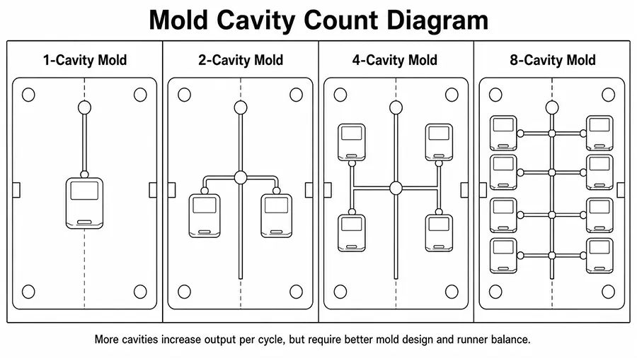
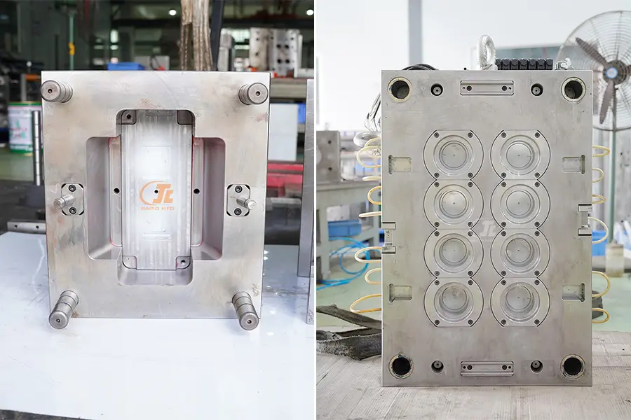
Cavity Layout and Runner System Design
Final part quality depends a lot on melt delivery and positioning of the cavity. This section deals with the effect of runner geometry on the uniformity and balance of filling in each individual impression.
Layout Configurations
Fill balance and mold base size is determined by the physical arrangement of cavities:
- Linear (in-line): Easy and inexpensive to process. Acceptable for 2 cavities but creates unequal runner lengths at 4+ cavities.
- Circular (radial): All cavities are at the same distance from the sprue. Naturally balanced. Common for 4, 6 and 8 cavities.
- H-pattern (branching): Geometrically balanced for 4, 8, 16 and 32 cavities. The industry standard for high cavity production tools in which all flow paths are equal in length, cross section and number of turns.
- Stack mold: Two or more faces of the mold stacked on a shared center section. It increases the production by twice without a rise in the clamping force. These are best suited for high volume thin wall parts in situations where machine tonnage is a limiting factor.
Maintaining Part Quality in Multi-Cavity Molds
The mold designers need to be aware of the fact that cooling uniformity, and venting are as important as fill balance. Lack of evenness in heat extraction will lead to uneven shrinkage of cavities. A separate or a balanced cooling circuit should be provided for each cavity.
Vent all cavities at the last fill point. Furthermore, all cavities should be machined from the same batch of steel and be within the same tolerance, while cavity-to-cavity variation needs to be maintained within ±0.005 mm.
Note: It is important to validate the multi cavity mold design with Mold-Flow Simulation (Moldex3D / Autodesk Moldflow) before cutting the steel.
Common Design Mistakes to Avoid
Errors in the engineering process can result in delays and disastrous changes to the tools. To protect your budget and product launch schedule, don’t make these common mistakes.
- Failure to check the size of the shot: Clamping tonnage is often checked, but barrel capacity is not. Even if a tool fits into the clamp, it may over fill the barrel, resulting in inconsistent shot weights, flash and poor material.
- Not analysing and sticking to powers of 2: 8 cavities is not necessarily better than 6. Non standard counts sometimes are preferred based on runner geometry, platen constraints and part geometry. Add the numbers first.
- Not accounting for the time to validate for each cavity: Every cavity needs sample shots, dimensional measurement report and steel correction. 16-cavity molds result in 16 times the FAI effort – and that directly correlates with delayed production start.
- Lack of maintenance access: Close cavities do not allow for a proper insertion, maintenance of the ejector pins and vent re-work. Therefore always leave a gap of at least 15 – 20 mm between the boundaries of the cavity.
- Investing in overbuilding for predicted volumes that are not realized: Make sure that demand forecasts are validated before investing in high cavity tooling. Often the best risk management plan is to take a phased approach – start with 4 cavities and later design a mold base to accept 8.
To Sum Up
The optimum number of cavities is not the maximum number that can be accommodated in a machine but the one that is compatible with the production requirements, part geometry and overall project economics. Use the volume formula, impose the tonnage and shot-size limitations, execute the cost crossover model and validate using simulation. Your answer is the number that meets all four at a time.
Ready to streamline your production? Allow RJC to determine your ideal cavity count and precision-engineer your mold now. Call our injection molding professionals today!
Related Questions
Q1: What is the standard formula for calculating injection mold cavity count?
Use N = (Q × t_c) / (T × 3,600 × η), then cross-check against clamping tonnage and barrel shot-size limits. The lowest result from all three constraints is your design ceiling.
Q2: What is the distinction between a multi-cavity mold and family mold?
Multi-cavity mold is a mold that creates more than one copy of a part at a time. Whereas a family mold makes two or more various parts in a cycle.
Q3: Clamping tonnage restricts the number of mold cavities, how?
Multiply the projected area of a single cavity (cm²) by the average cavity pressure (normally 0.3 to 0.7 tons/cm² depending on the material). Divide available machine tonnage by such a product. The outcome is the highest number of cavities that the machine can hold closed without flash or damage to the mold.
Q4: Does the increase in cavities affect part quality?
Yes. An increase in the number of cavities increases the fill imbalance, cooling non-uniformity, and cavity-to-cavity dimensional variability. In the absence of balanced runners and symmetric cooling circuits, the scrap rates increase in direct proportion to the number of cavities.
Q5: What is the 80% barrel capacity rule in multi-cavity mold design?
Shot volume of all cavities plus runner system should not exceed 80% of the maximum barrel capacity of the injection unit. High shot percentages (>80%) result in variable weights and material degradation due to too long residence time.