


When we first made the mold for a polycarbonate part, everything seemed to be going perfectly. The CAD model matched the design and the mold depth was machined with great precision. The first molded part looked very clean.
But when we measured the prototype, several features measured almost 0.3 mm small. At that moment, I realized that shrinkage is not just a number on a data sheet. It is a critical factor which affects the final part, and it is really important to pay attention to it at the design stage.
This blogpost presents all the lessons I have learned about PC shrinkage in injection molding. I will discuss the fundamentals, real world problems, best design guidelines and process controls. If you design or engineer PC parts, this guide will help you avoid common mistakes and obtain better results.
Understanding Shrinkage in Injection Molding

Shrinkage in Injection Molding
What is Shrinkage?
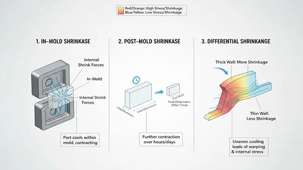
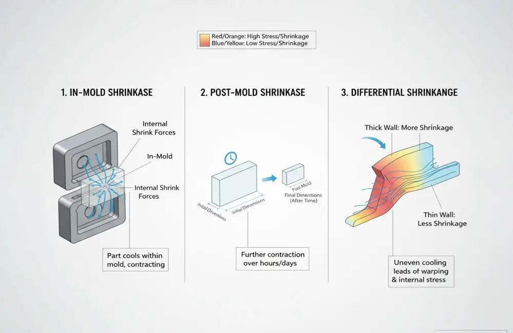
In simple terms, shrinkage happens when molten plastic cools and solidifies inside molds which causes its dimensions to reduce. All polymers shrink but the amount and direction can differ. There are three main types of shrinkage:
- In-mold shrinkage: The material shrinks as it solidifies while under pressure.
- Post-mold shrinkage: The part keeps contracting as it cools further after leaving the mold.
- Differential shrinkage: Uneven shrinkage occurs because of cooling speed, part shape or how fillers are arranged.
PC – An Amorphous Thermoplastic
Polycarbonate or PC is basically an amorphous plastic so it does not have a crystalline structure. Because of this, it shows:
- Lower shrinkage than semi-crystalline plastics like PA66 or POM.
- More uniform shrinkage in every direction which means less warping.
Still I have seen many PC parts warp – so shrinkage does not always behave as expected.
Typical Shrinkage Rates for PC
| Material | Shrinkage | Type |
| PC | 0.5 to 0.7% | Amorphous |
| PC + 20% GF | 0.4% | Filled |
Usually unfilled PCs have a shrinkage rate between 0.5% and 0.7%. This value can change depending on many factors:
- The brand or formulation
- Processing settings
- Wall thickness & shape of the part
Adding fillers such as glass fiber lowers the shrinkage rate. For example:
- PC with 20% glass fiber (GF) shrinks by about 0.4%
- PC with 40% GF can shrink as little as 0.1%
However the way fibers line up can cause shrinkage to differ by direction – particularly in parts with long flow paths. In some tests we saw shrinkage along the flow direction reach about 0.3%. Whereas in those across the flow it dropped to around 0.1%.
Why Shrinkage Matters — Our Experience
Dimensional Accuracy
If you do not take shrinkage into account your part may turn out smaller than planned even when the mold cavity and CAD design match exactly. This issue is particularly important for parts which need tight tolerances as it can impact how well they function.
For instance a client once faced a problem with a PC lens housing that did not fit tightly in its snap-fit assembly. They had used a 0.5% shrinkage rate but the actual part shrank by 0.7%. On a 100 mm part, this 0.2% difference resulted in a 0.2 mm gap which was not acceptable.
Want to know how we found and fixed the problem? See the full case study below.
Assembly & Fit
When different materials such as ABS and PC are used, their shrinkage rates can vary. These differences may cause loose fits, misalignment or even clamping failures. In order to avoid these problems, you must compensate for shrinkage accurately—particularly in housings with multiple parts.
Warpage & Internal Stress
Usually the PC remains stable but uneven cooling can cause warpage or it can leave residual stresses. Parts with thick ribs or walls that are not uniform may twist as they cool down. In one case, a customer’s flat display window bent by 1 mm across its width because the cooling was not balanced.
Tooling Costs
Mold shrinkage errors are very expensive to fix. If a part comes out too small, you might need to re-machine the mold or in some cases make a new one. For this reason I always tell my team to double-check shrinkage rates before they finish the mold design.
Also See: How To Solve The Bubble In The PC Plastic Injection Molding Process.
What Factors Affect PC Shrinkage Rate During Molding
Polycarbonate shrinkage does not happen by chance. Many factors interact to influence it. For controlling dimensions accurately in PC molding, it is very important to know these factors.
Material Properties
- Filler content: Adding more filler lowers the shrinkage rate.
- Moisture content: PC absorbs moisture so it is necessary to pre-dry the material.
- Molecular orientation: Flow stretches the polymer which can cause shrinkage in certain directions.
Process Parameters
- Mold temperature: Raising the mold temperature improves packing and reduces shrinkage.
- Cooling rate: If cooling happens quickly, residual stress increases and shrinkage becomes uneven.
- Holding pressure/time: Longer holding times push more resin into the cavity and help prevent shrinkage.
- Ejection temperature: Removing the part from the mold too soon allows extra shrinkage to occur outside the mold.
Geometry
Part design also performs an important part:
- Parts with thick sections usually shrink more than thin ones.
- Gate location and the direction of flow affect how the part fills and orients.
- Sharp corners and walls with uneven thickness create areas of different shrinkage.
How to Reduce PC Shrinkage in Injection Molded Parts
If designers do not calculate shrinkage in injection-molded polycarbonate parts at an early stage, precision can suffer. Experts use several methods, from adjusting CAD models to running moldflow simulations, to stay ahead of shrinkage issues.
CAD Design and Mold Compensation
Designers account for average shrinkage rates in CAD models. For unfilled PC, the rate is 0.006 in/in while for 20% GF PC, it is 0.004 in/in. For example a 100 mm cavity may need to measure 100.6 mm to offset expected shrinkage. Teams often keep inserts adjustable so that fine-tuning can be done.
Process Optimization
Research at the Institute of Technology Ladkrabang shows that melt temperature and packing pressure have a profound impact on PC shrinkage. Both lowering the melt temperature as well as raising packing pressure help reduce volume shrinkage.
Professionals use DOE (Design of Experiments) to test variables like cooling time, hold pressure and mold temperature. In one case, increasing mold temperature by 10 °C led to a 20% reduction in shrinkage variance.
Moldflow Simulation
Simulation tools such as Moldex3D or Autodesk Moldflow help predict warpage and shrinkage before mold fabrication. However simulation results do not always match real-world outcomes. To improve accuracy, professionals should calibrate simulation data with actual measurements. Product designers, engineers and material specialists benefit from this approach.
Material Selection
Switching from unfilled PC to glass-filled PC can lower shrinkage – particularly for large panels or structural components. Effective shrinkage control is a combination of simulation software, science and hands-on experience. When shrinkage locations are unclear, it is recommended to consult polycarbonate injection molding experts.
Real Case – Shrinkage Gone Wrong And How We Fix It
A medical equipment maker which has been working with us for years came to us with a serious problem. The company was about to launch a diagnostic device. It had ordered a precision-molded PC lens housing – the clear cover that protects and aligns its delicate optical system.
The Challenge
After the first production run, dimensions did not meet spec. A nearly 0.2 mm shift knocked the optics out of alignment. Such an error is unacceptable in hardware where microns make a difference.
The Symptoms
- Visible warpage spreading over the lens surface
- Poor fit within the optical assembly
- Parts was unable to line up with mating components even though the mold matched drawings
The team molded unfilled polycarbonate and applied a 0.5% shrinkage rate that is taken from generic datasheets but final parts still didn’t match the targets.
Our Investigation
When the client contacted us, our team examined the situation in four main areas:
- Material Review
Our engineers inspected the actual resin lot and noted a modest rise in MFI (Melt Flow Index) and moisture content. Since a PC absorbs moisture, even a small amount can change warping or shrinkage. - Processing Parameters
We looked at the molding report and found that the mold temperature was set 12 °C below the recommended level. This setting can increase shrinkage and add internal stress to the parts. - Packing & Holding Pressure
The holding time on the machine lasted only 2 seconds. This short duration did not allow enough compensation for material pullback as the part cooled. As a result voids formed and packing was uneven. - Cooling System & Ejection Timing
The cooling system was unbalanced and the parts were ejected before they fully stabilized. Because of this early ejection, post-mold shrinkage and changes in dimensions occur.
Our Solution
We addressed the problem with several targeted actions:
- We pre-dried the resin at 120 °C for 4 hours.
- The mold temperature is increased to 95 °C.
- We raised the hold pressure and extended the hold time to 6 seconds.
- Our engineers balanced the cooling system and lengthened the dwell time.
- We updated the shrinkage assumption to 65% which was confirmed with Moldflow simulation.
I also recommended that the client change their shrinkage assumption to 0.65% based on our test coupon measurements.
The Outcome
During the following production run:
- Dimensional accuracy improved by an average of 0.18 mm.
- Warpage dropped by almost 50%.
- The optical alignment issue was fully corrected.
- Assembly tolerances returned to the needed range.
Most importantly the client was able to keep their product launch on track. They did not need to rework the mold or postpone testing. This case clearly showed that shrinkage is not a fixed value from a datasheet but rather a variable factor that is shaped by every stage of the process.
Shrinkage Compensation Checklist for Injection Mold Design
Effective injection molding starts before the plastic meets the mold. In order to control shrinkage at every stage, use this checklist
- Dry PC resin thoroughly at 120 °C for 2 to 4 hours.
- Ask your specific material supplier to confirm shrinkage rates.
- Run simulations, but always check results with test plaques.
- Include expected shrinkage in your CAD models.
- Keep wall thickness uniform throughout the part.
- Design the mold with an optimized cooling system.
- Change hold pressure and time to enhance packing.
- Begin with mold inserts that can be adjusted if possible.
- Inspect for shrinkage within 24 hours after molding.
- Record shrinkage data for future projects.
Also See: Defects In The Product Itself Caused By Injection Molding.
Conclusion
Many overlook shrinkage in injection molding but it performs an important part in getting accurate dimensions. This is particularly important for PCs where tight fits or clear parts are common. You must plan for shrinkage, control it and compensate for it.
If you are planning to start a project with a PC, do not rush into mold design. First check your assumptions, make test parts and measure real shrinkage. This process helps you avoid extra costs, wasted time and preventable problems.
If you face PC shrinkage challenges, you can reach out to us for expert advice.