

In injection molds, a lifter is an ejection mechanism used to release side undercuts and is usually installed on the moving-half side of the mold. During ejection, it not only moves forward but also generates lateral displacement, allowing the side undercut on the part to be released first and then enabling complete demolding.
This mechanism is commonly used for undercuts, internal undercuts, reverse features in side holes, and localized wrap-around features. In these areas, ordinary ejector pins can only push the part along the mold-opening direction and cannot eliminate lateral interference. The value of a lifter lies in combining “ejection” and “side release” into the same demolding action.
I. What Is a Lifter?
A lifter is part of the mold ejection system, but it works differently from a standard ejector pin. A standard ejector pin mainly provides straight-line ejection and is suitable for conventional structures without side undercuts. A lifter, by contrast, is used in areas with reverse features and moves obliquely at a preset angle so the plastic part can avoid lateral interference during demolding.
Therefore, a lifter is not meant to solve a general pushing problem; it is meant to release undercuts. Whenever a product includes side wrap-around features, internal snap hooks, or localized reverse features, the lifter is often indispensable.

II. Where Is a Lifter Commonly Used?
The most common applications of lifters are usually concentrated in internal or locally constrained areas of a product, mainly including the following categories:
- Undercuts
An undercut is a feature on an injection-molded part that creates reverse interference relative to the mold-opening direction. When the mold moves along the opening direction, this feature prevents the part from separating smoothly from the core or cavity. Undercuts may appear on the exterior or inside of the product and include snap hooks, steps, bosses, and reverse steps inside holes. In essence, an undercut is defined not by shape alone, but by the relationship between the feature and the demolding direction.

- Internal Undercuts
Snap-fit features are often designed inside housing-type products for assembly and retention. If the snap feature forms a reverse feature, the product cannot be removed directly from the mold after opening and must rely on a lifter for lateral release.

- Reverse Features in Internal Holes or Grooves
Some functional parts use localized wrap-around features at hole edges or groove edges. These structures are not large, but they have a clear effect on demolding. Without lateral clearance, the plastic part can easily be trapped in the mold.
- Inner-Wall Bosses or Stop Features
Some products add local bosses inside the part for positioning, stopping, or assembly strength. If these areas form undercuts, a lifter is often a common solution.
- Small Undercuts Unsuitable for Sliders
When the undercut area is small, located toward the interior, and mold space is limited, using a slider may not be economical. In such cases, a lifter is usually more suitable.
In general, small, internal, and localized undercuts are more likely to be handled with lifters, whereas larger features with long external side-core-pulling distances are better suited to sliders.
IV. How Does a Lifter Work?
The core of a lifter is compound oblique motion.
After injection molding is completed, the plastic part cools and shrinks inside the mold and usually remains on the moving-half side when the mold opens. At this point, the ejection mechanism begins to move forward, and the lifter advances together with the ejection system. Because the lifter itself is angled, or because it forms an oblique guiding relationship with the guiding structure inside the mold, it does not move only in a straight line as it advances; it also moves sideways at the same time.

This action can usually be understood in three stages:
Stage 1: Contact with the Product
After the mold opens, the ejection system starts, and the lifter first contacts the reverse-feature area of the plastic part.
Stage 2: Side Release
As ejection continues, the lifter moves along the preset angle and gradually produces lateral displacement, releasing the side undercut that is holding the product.
Stage 3: Overall Demolding
Once the undercut is fully disengaged, the product loses its lateral restraint and is then fully ejected from the mold.
Whether a lifter can work reliably does not depend on whether it moves, but on whether its motion path is correct. An improper angle, insufficient stroke, a weak load-bearing area, or unstable guiding can turn a mechanism that should solve a problem into a new source of problems.
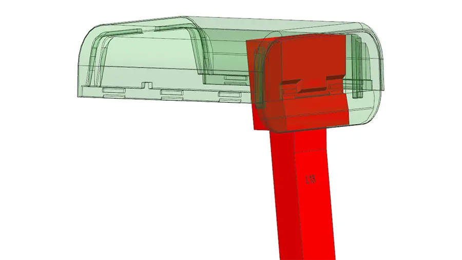
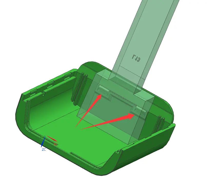
V. Case Study
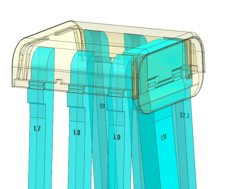

As shown in the figure, this is a plastic charger housing. The transparent portion is the plastic part itself, and the cyan portions are the lifter assemblies. This product has internal undercut features at multiple locations (such as areas L7, L8, L9, and L13), and these features are relatively dense while available space is limited. To address this, the design uses multiple lifters arranged in parallel, with each lifter corresponding to one internal undercut area so that localized side core pulling can be performed independently.
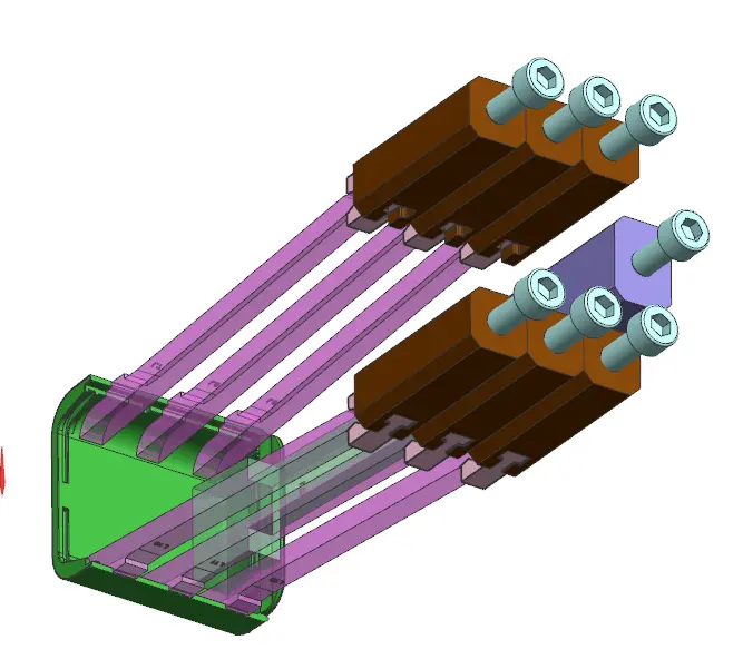
The lifter structure is linked with the ejection system and moves synchronously with the ejector plate during mold opening. The lifter slides outward along a preset angle (3°), thereby eliminating interference from the product’s internal undercuts and achieving smooth demolding. The lifter head is shaped to match the product’s internal undercut geometry, ensuring that the side-core-pulling stroke precisely matches the product structure while also avoiding interference and drag marks.

In this design, the following key points were emphasized:
- Stroke matching: ensure that the lifter travel is greater than the undercut depth and leave a safety clearance;
- Strength and rigidity: when multiple lifters are arranged in parallel, avoid slender structures that may deform or break;
- Guiding and positioning: use the lifter seat and guiding/sliding structure to ensure stable motion and prevent uneven wear;
- Spatial interference control: verify motion interference among multiple lifters;
- Product appearance protection: polish the contact surfaces between the lifter and the part, or add draft, to avoid whitening and scratching.
This structure effectively solves the demolding problem for complex internal undercuts while keeping the mold compact and the motion reliable. It is suitable for mold designs of small electronic housings with multiple internal undercuts.
This case involves an injection mold for a charger housing. Because the product has obvious reverse features (internal undercut locations) on the side wall and internal structures, conventional ejection cannot achieve smooth demolding, so a lifter mechanism is used for side core pulling and synchronized ejection.
VI. Common Problems in Lifter Design
The difficulty of lifter design lies not in the concept, but in control of the details. Many issues do not arise from whether a lifter should be used, but from how it is arranged.
- Unreasonable Angle
If the angle is too small, side release is insufficient; if it is too large, friction and ejection resistance increase, motion becomes less smooth, and wear accelerates.
- Insufficient Stroke
If the lifter has not fully released the undercut before the product starts overall demolding, the most common results are drag marks, whitening, or sticking.
- Weak Load-Bearing Location
If the lifter contacts a thin wall, a sharp corner, or the root of a snap hook, whitening and deformation can easily occur during ejection; in severe cases, the feature may even break.
- Inadequate Fit Accuracy
A lifter is a moving component and therefore has high requirements for guiding, clearance, and machining accuracy. Poor fit can lead to wear, looseness, or sticking in mass production.
- Focusing Only on Demolding and Not on Marks
The fact that the lifter can remove the product does not mean the solution is reasonable. If its motion path passes through an appearance-sensitive area, the product surface can easily be left with drag marks, scratches, or indentations.
We previously encountered a type of housing part for which the issue was initially blamed on brittle material. After reviewing the structure, however, we found that the real problem was that the load point of the lifter pressed on the root of a snap hook, where local strength was already weak, so whitening naturally occurred during ejection. Many issues that seem like material or process problems ultimately need to be judged by returning to the mechanism itself.
VII. Why Are Lifter Marks Harder to Resolve Than Ejector Pin Marks?
Ejector pin marks are usually point-like traces caused by localized vertical force, whereas lifter marks are often associated with a motion process. During operation, the lifter applies both ejection force and lateral friction. As a result, if the angle, position, or surface condition is not properly controlled, what remains is not just a single point, but possibly a drag mark, scratch, or indentation along a path.
This is also why lifter problems are less suitable for being solved only through later machine adjustment. Parameter adjustment can improve some symptoms, but if the root cause lies in the lifter angle, stroke, or contact position, process tuning can only alleviate the issue, not eliminate it.
VIII. How Can You Judge Whether a Lifter Design Is Reasonable?
A mature lifter solution should meet at least the following conditions:
- The undercut can be completely released
- The ejection action is smooth, with no interference or sticking
- The load-bearing area has sufficient strength and is not prone to whitening or deformation
- Marks are controllable and do not affect appearance or assembly
- The mechanism is wear-resistant and stable enough to support mass production
When judging whether a lifter is reasonable, the focus is not on whether the product can come out, but on whether demolding is stable, whether the product is damaged, and whether the mechanism can work over the long term. Being able to demold is only the baseline; being able to run in production is what proves the solution.
IX. Conclusion
A lifter is an important mechanism in injection molds for handling side undercuts. Through oblique motion, it completes both undercut release and demolding during ejection, making it suitable for common structures such as snap hooks, internal undercuts, and localized reverse features.
For products with side undercuts, a lifter is often not optional but a key factor that determines whether the demolding solution can actually be implemented.
If you would like to read more articles about injection mold components:
What Is a Slider in Injection Molding? A Case Explanation
Plastic Mold Gates Types, Selection, and Practical Case Studies