


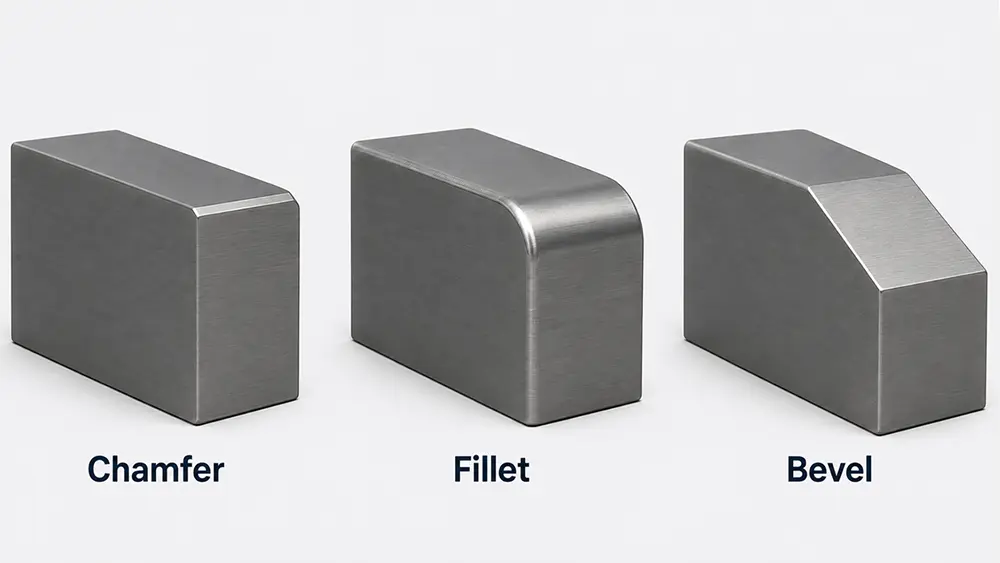
In product design and manufacturing, part edges are rarely left as sharp right angles. Chamfers, fillets, and bevels all modify edge geometry, but they differ significantly in shape, function, and manufacturing method. This article explains their main differences and how to choose between them for CNC-machined and injection-molded parts.
1. Key Differences Between Chamfers, Fillets, and Bevels
| Comparison | Chamfer | Fillet | Bevel |
| Basic shape | A relatively small flat angled surface | A rounded transition | An inclined edge or surface |
| Main dimensions | Width and angle | Radius | Angle, width, or length |
| Main purpose | Assembly guidance and sharp-edge removal | Stress reduction and smooth transitions | Weld preparation, structural connections, and appearance |
| Common locations | Hole openings, shaft ends, and part edges | Internal corners, external corners, rib roots, and boss bases | Plate edges, welded joints, and large inclined surfaces |
| Effect on strength | Limited improvement | Generally distributes stress more effectively | Depends on the structure and application |
| Common manufacturing methods | CNC milling, turning, and grinding | Form tools, ball-end mills, and mold forming | Milling, grinding, and cutting |
| Machining cost | Usually lower | May be higher | Depends on size and manufacturing method |
From a geometric perspective, a chamfer can be considered a specific type of bevel. However, these terms are not used consistently across industries, companies, and CAD software. Engineering drawings should therefore clearly specify the required angle, width, and location.
2. What Is a Chamfer?
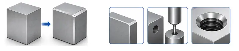
Chamfer Geometry
A chamfer is a flat angled surface formed along a part edge. It may be machined or created directly during molding or casting. It is commonly used to remove sharp edges, guide assembly, and finish hole openings or thread entrances.

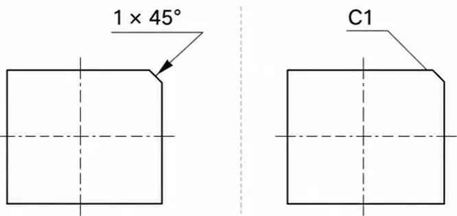
On engineering drawings, a chamfer may be specified as “1 × 45°,” meaning a 1 mm chamfer at an angle of 45°. “C1” also commonly indicates a 1 mm, 45° chamfer, although the exact meaning should follow the drawing standard being used. A 45° angle is the most common, but 30°, 60°, and other angles may be selected to meet specific functional requirements.

Typical Chamfer Applications
Shaft ends: Help the shaft enter a hole or bearing
Thread entrances: Reduce damage and jamming at the start of the thread
Bearing mounting areas: Guide the bearing smoothly into position
Hole openings and locating-pin entrances
External edges of CNC-machined parts
Areas where sharp edges and burrs must be removed
Compared with a fillet, a standard small chamfer is generally easier to machine. It can be produced quickly with a chamfer mill, end mill, or turning tool. For this reason, chamfers are often used for general edge treatment when there are no special load-bearing requirements.
3. What Is a Fillet?
Fillet Geometry
A fillet is a rounded transition that connects two intersecting surfaces, replacing an abrupt sharp corner with a smooth curve.
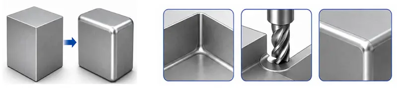

On engineering drawings, fillet size is generally specified with the radius symbol R. For example, R1, R3, and R5 indicate fillet radii of 1 mm, 3 mm, and 5 mm, respectively.
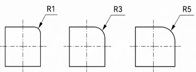

In most mechanical parts, internal fillets are used to reduce stress concentration and accommodate the geometry of rotary cutting tools, while external fillets are mainly used to remove sharp edges, improve handling comfort, and enhance appearance. Fillets in injection-molded parts are commonly added at wall intersections, rib roots, and boss bases to improve melt flow and reduce localized stress and the risk of cracking.
Typical Fillet Applications
Internal corners of CNC-machined pockets
Corners of structural parts and brackets
Wall intersections in injection-molded parts
Rib roots
Boss bases
Handles and other user-contact areas
Parts subjected to vibration or cyclic loading
4. What Is a Bevel?
Bevel Geometry
A bevel is an inclined edge or surface created by removing material from a part edge or by forming the geometry directly during molding or casting. The term is broader than chamfer and may describe a large inclined surface, a welding groove, or a cutting edge.
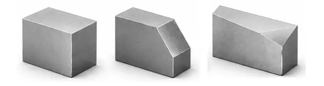

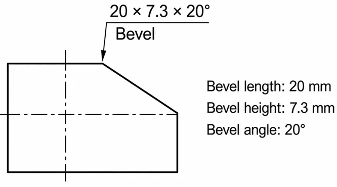
On engineering drawings, a bevel is generally specified by its angle and dimensions.

Typical Bevel Applications
Edges of plates prepared for welding
Tools and cutting edges
Edges of glass, wood, or metal panels
Large inclined surfaces
Structural connection areas
Decorative product edges
In welded structures, bevels can form V-shaped, X-shaped, or other groove configurations, allowing the weld to penetrate deeper into the plate.
Bevels are also widely used for appearance in consumer products. Metal panels, electronic housings, and decorative components can use broad inclined surfaces to create stronger light-and-shadow effects and a more clearly defined profile.
5. How to Choose for CNC Machining
Selection Guide
| Requirement | Recommended Feature | Main Reason |
| Remove sharp external edges | Chamfer | Simple to machine and relatively inexpensive |
| Guide shafts, pins, or screws during assembly | Chamfer | The flat angled surface provides guidance |
| Reduce stress at structural corners | Fillet | The curved transition distributes loads smoothly |
| Machine internal pocket corners | Fillet | Matches the geometry of rotary cutting tools |
| Create a large inclined surface | Bevel | Better suited to greater widths and angles |
| Produce a welding groove or cutting edge | Bevel | Provides the required inclined geometry |
| Improve part appearance or feel | Fillet or bevel | Depends on the intended visual style |
Consider Tool Accessibility
When designing fillets and bevels, consider whether the cutting tool can reach the required area.
A small internal fillet in a deep pocket may require a long, narrow tool. As tool diameter decreases and overhang increases, machining rigidity is reduced, and the feed rate may need to be lowered. Increasing the internal corner radius, where possible, allows the manufacturer to use a larger-diameter tool and improve machining efficiency.
Large bevels may require an angled tool, multiple passes, or an additional setup. When an inclined surface cannot be reached easily on a standard three-axis machine, 4-axis or 5-axis machining may be required.
Avoid Unnecessary Small Fillets
Many CAD models include small fillets on nearly every edge, even when those fillets serve no functional purpose.
Unnecessary fillets can increase:
- CAM programming time
- The number of cutting tools
- Toolpath complexity
- Inspection difficulty
- Overall manufacturing cost
When an edge only needs deburring and has no strict geometric requirement, the drawing can simply specify “Remove sharp edges” or “Break sharp edges,” rather than assigning a precise small fillet to every edge.
6. How to Choose for Injection-Molded Parts
Selection Guide
| Location or Requirement | Recommended Feature | Main Reason |
| Wall intersections | Fillet | Improves material flow and stress transition |
| Rib roots | Fillet | Reduces stress and the risk of cracking |
| Boss bases | Fillet | Improves stability at the connection |
| Hole openings or assembly entrances | Chamfer | Helps screws, pins, or inserts enter |
| Handles and contact edges | Fillet | Improves comfort and removes sharp edges |
| Large inclined cosmetic surfaces | Bevel | Creates a clearly defined angled profile |
| Side walls along the ejection direction | Draft | Draft should be used instead of a chamfer |
Injection-molded parts generally rely more heavily on fillets than CNC-machined parts. When molten plastic passes through a sharp corner, its flow direction changes abruptly, which may contribute to localized stress, uneven filling, or weld-line problems.
A Chamfer Is Not a Substitute for Draft
A chamfer only modifies a small area at the edge of a part, while draft is applied along the entire side wall in the mold-release direction. Even when a chamfer is added, a side wall that remains completely vertical to the parting plane can still create high friction during ejection and may become scratched or damaged.
Use Large Bevels Carefully
Bevels can be used to create inclined cosmetic surfaces on injection-molded parts, but large bevels require careful consideration of wall thickness and mold structure.
When a bevel significantly increases local wall thickness, it may cause sink marks, surface depressions, or uneven cooling. If the bevel direction does not align with the mold-opening direction, it may create an undercut that requires a slide or lifter, increasing mold cost.
Large bevels should therefore be evaluated not only for appearance, but also for wall thickness, parting-line location, ejection direction, and mold-manufacturing requirements.
7. Case Study—Ashtray
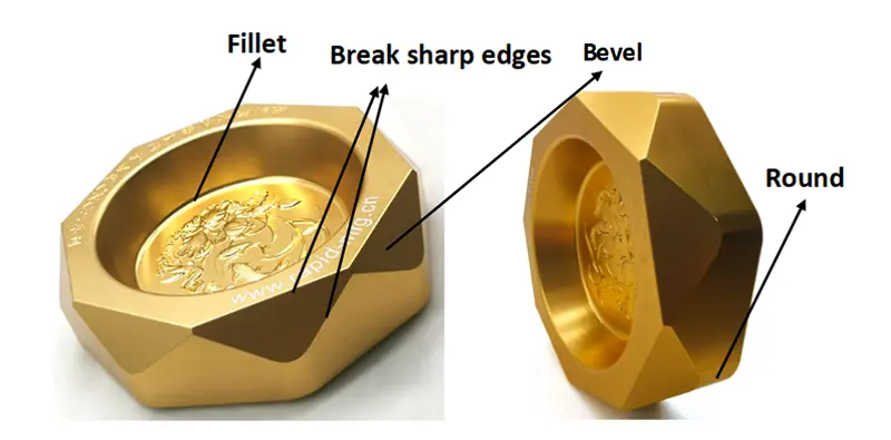

As shown above, we chose large bevels for the outer surfaces of this ashtray. The multiple machined facets create richer light-and-shadow effects, giving the product a stronger three-dimensional appearance and greater decorative appeal. A simple edge break is applied where the bevels meet to remove burrs and sharp edges. Because these edges do not require precise small chamfers or fillets, this approach simplifies machining and helps control cost.
The long side edges use external fillets to make the ashtray safer and more comfortable to handle. A fillet is also added where the inner wall meets the bottom of the cavity, making the part easier to machine and clean while reducing ash buildup.
FAQ
Q1: Can fillets on plastic parts affect the parting line?
Yes. A fillet that crosses the parting surface may make the mold structure and parting-line treatment more complicated.
Q2: Can polishing change chamfer or fillet dimensions?
Yes. Polishing removes a small amount of material, so very small chamfers and fillets may change slightly.
Q3: Can surface finishing affect the appearance of an edge?
Yes. Anodizing, electroplating, and coating may produce differences in color or film thickness around edges.
Q4: Do edge dimensions require tight tolerances?
Only when they affect assembly, sealing, or appearance. Tight tolerances on nonfunctional edges increase manufacturing cost unnecessarily.
Q5: Why can a small chamfer appear less visible after plastic molding?
Plastic shrinkage, mold polishing, and surface texture can make a small chamfer appear rounded or less defined. It should therefore not be designed too small.