In our previous article, Living Hinge Design Guide, we mentioned that fillets can effectively reduce stress concentration and extend the service life of living hinges. In fact, fillets are not limited to living hinges. They are an essential design feature in nearly all injection-molded parts. A properly designed fillet does more than improve appearance—it can also promote smoother melt flow, increase structural strength, reduce molding defects, and simplify mold manufacturing. For this reason, fillet design is a fundamental principle that should not be overlooked in plastic part design.
Why Do Injection-Molded Parts Need Fillets?
Improve Melt Flow
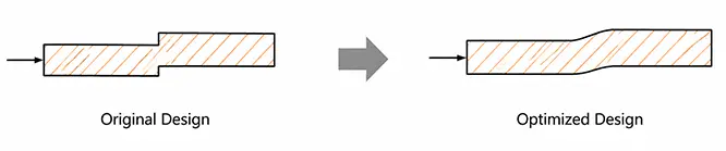
When molten plastic flows through the mold cavity, a sharp corner can cause an abrupt change in the flow cross-section. This increases flow resistance and may even create turbulence or stagnant flow zones, raising the risk of defects such as short shots and weld lines.
By adding an appropriate fillet, the melt can pass through the corner more smoothly. This not only improves cavity filling but also enhances molding stability in geometrically complex areas. (As shown below)
Reduce Stress Concentration
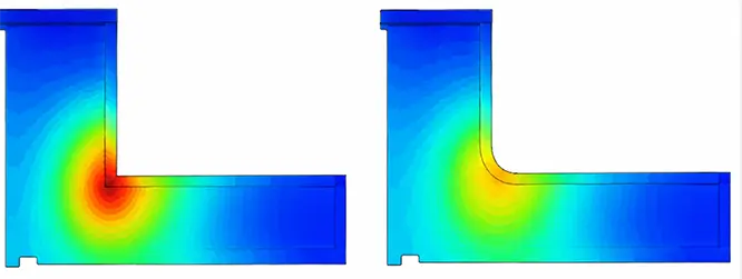
Sharp corners are among the most common locations for stress concentration in plastic parts. When the part is subjected to tensile, bending, or impact loads, stress tends to accumulate around these corners, increasing the risk of cracking.

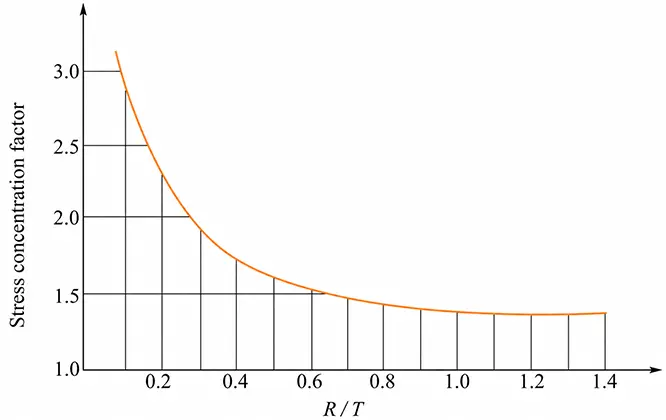
Fillets distribute the load more evenly and reduce peak local stress. As shown by the curve below, the effective stress concentration factor decreases rapidly as the radius R increases. By spreading stress over a larger surface area, a fillet helps prevent rapid deformation or cracking in load-bearing regions.
Improve Part Strength and Service Life
Once stress concentration is reduced, the overall strength and durability of the part also improve. In areas exposed to repeated loading—such as snap-fits, mounting holes, rib bases, and boss bases—a properly sized fillet can improve fatigue resistance and reduce the likelihood of fracture or damage during long-term use.
Reduce Mold Machining Difficulty
From a mold manufacturing perspective, a sharp external corner on the product usually corresponds to a sharp internal corner in the mold cavity. These internal corners are often difficult to machine directly with standard cutting tools and may require electrical discharge machining (EDM) or other special processes, increasing both cost and lead time.
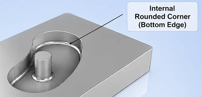
With a suitable fillet, most of these areas can be machined directly using ball-end mills or end mills. This improves machining efficiency, reduces tool wear, and can also help extend mold life.
Promote Uniform Cooling
Sharp corners are often associated with local changes in wall thickness, which can cause those areas to cool at a different rate from the surrounding material.
Uneven cooling increases residual stress and may lead to warpage, dimensional variation, or even sink marks. A well-designed fillet creates a smoother wall-thickness transition and more uniform heat distribution, improving the dimensional stability of the molded part.
Fillet Design
Fillet Radius Design
Determine the Fillet Radius Based on Wall Thickness
There is no single fixed value for fillet radius. It should be determined in relation to the part’s wall thickness.
A commonly used engineering guideline is:
The internal fillet radius (r) should be approximately 0.5 to 0.75 times the wall thickness (T).
The external radius (R) is generally equal to the internal radius plus the wall thickness.
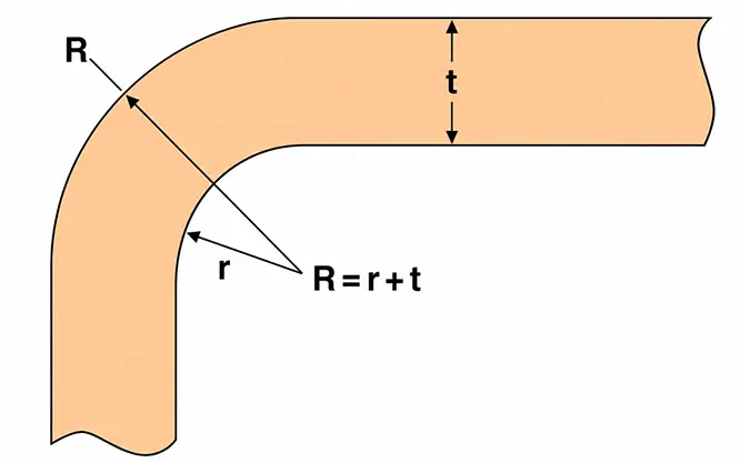
The purpose of this relationship is to maintain a relatively uniform wall thickness through the corner and avoid local thick sections that may cause sink marks, warpage, or uneven cooling.
For heavily loaded parts or parts made from engineering plastics, the radius may need to be increased appropriately. If structural constraints make it impossible to follow the recommended ratio, sharp internal corners should still be avoided wherever possible.
Avoid Fillets That Are Too Small or Too Large
Some designers assume that adding even a very small radius is enough. In practice, however, extremely small fillets, such as R0.1 or R0.2, provide only limited improvement in stress distribution while making mold machining more difficult.
At the same time, a larger fillet is not always better. An oversized radius can create a local increase in wall thickness, which slows cooling and may result in sink marks or warpage. The radius should therefore be selected to meet structural requirements without unnecessarily increasing section thickness.
Use Larger Fillets in High-Stress Areas
A larger fillet radius should be considered in areas that carry loads or undergo repeated deformation, including:
- Rib bases
- Boss bases
- Snap-fit connection areas
- Living hinge transition areas
- Areas around mounting holes
- Corners in load-bearing structures
These locations are naturally prone to stress concentration. A larger radius creates a smoother transition, reduces local stress, and improves long-term durability.
Adjust the Fillet According to Material Properties
Different plastics respond differently to stress concentration.
Materials such as ABS and PP have relatively good toughness and are generally more tolerant of fillet size. PC and PMMA, on the other hand, are more sensitive to stress and typically require more careful fillet design. For reinforced materials such as glass-fiber-reinforced nylon, the fibers can further intensify local stress concentration, making it especially important to avoid sharp transitions.
Fillet Design Principles
Fillets at Corners Must Maintain Uniform Wall Thickness
This is one of the most important principles in fillet design.
If an internal fillet is added without adjusting the corresponding external radius, the corner will become locally thicker, increasing the risk of sink marks and warpage. Internal and external radii should therefore be designed together so that the wall thickness remains as continuous and uniform as possible.

Fillet Design Should Consider Mold Machining
Fillets affect not only the molded part but also the mold itself.
The design should take tool radius, machining method, and demolding requirements into account. Extremely small radii that are difficult or costly to machine should be avoided. For complex geometries, the radius should be reviewed with the mold engineer during the DFM stage.
Fillet Design Should Avoid Cosmetic Defects
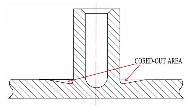
Fillets at the connection between the main wall and internal structural features—such as ribs, screw bosses, and snap-fits—must be designed carefully. Adding a fillet in these areas may create an excessively thick local section, which can cause visible sink marks on the opposite surface.
If a fillet is necessary to improve strength, the area should first be cored out or relieved before the fillet is added. A typical example is the volcano-style coring commonly used around screw bosses.
Fillet Design Example
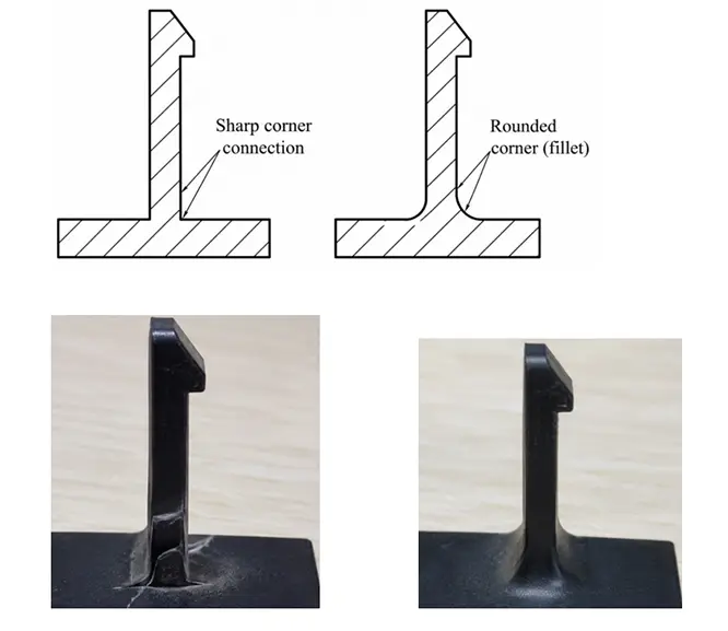
The following example comes from an electronic device back cover that we previously manufactured for a customer. Its snap-fits needed to be repeatedly removed and reinstalled during maintenance and internal component inspection, making it a typical case in which fillet design was critical.
During assembly and disassembly testing, the original snap-fit design developed whitening and fine cracks at the root after repeated bending because the transition was close to a sharp right angle. Based on the snap-fit wall thickness, we increased the root fillet and adjusted both the internal and external profiles to create a smoother transition and more uniform wall thickness.
After optimization, stress concentration during testing was significantly reduced, while both the repeated assembly life of the snap-fit and the molding stability of the part were improved.
Need to Optimize Your Plastic Part Design?
If you are developing a new injection-molded product, RJCMold provides one-stop injection molding services from DFM analysis and mold design to volume production. We help identify potential issues early in the design stage and improve the manufacturability of your parts. Upload your drawings today to receive a DFM review and injection molding quotation.
FAQ
Q1: Do All Corners Need Fillets?
Not necessarily. However, fillets are recommended for most internal corners, especially in load-bearing areas or locations through which the melt must flow.
Q2: What Is the Relationship Between the Internal and External Radius?
The external radius is generally equal to the internal radius plus the wall thickness, which helps maintain a uniform section through the corner.
Q3: What Is the Difference Between a Fillet and a Chamfer?
A fillet creates a curved transition and helps reduce stress concentration. A chamfer creates a straight, angled transition and is more commonly used for assembly, deburring, or guiding components into position.
Q4: Do Fillets Increase Mold Cost?
A properly designed fillet usually does not increase mold cost and may actually simplify machining. Only extremely small radii or special fillet requirements are likely to add manufacturing cost.