If you are designing an injection-molded part, you may quickly run into this problem: the wall thickness can no longer be increased, but the part is still not rigid enough. So how should ribs be added? How thick and tall should they be, and how far apart should they be spaced, so that they actually improve strength without causing sink marks, warpage, or ejection problems?
This rib design guide for injection molding focuses on these practical design questions and explains the key dimensions, layout, and structural design considerations for ribs.
1. Key Rib Dimensions for Injection Molding
There is no single rib size that works for every plastic material or every part. In practice, rib dimensions are usually determined in relation to the nominal wall thickness, then adjusted according to the material, part geometry, and cosmetic requirements. In the following sections, T represents the nominal wall thickness of the part.
1) Rib Thickness
Rib thickness is one of the most important dimensions to control. The thickness at the rib base is generally used as the design reference, with a common recommendation of approximately 40%–60% of the nominal wall thickness, or: Rib thickness ≈ 0.4T–0.6T
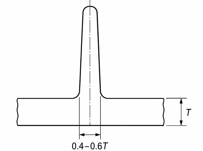
Thicker ribs are not necessarily better. Where a rib joins the main wall, the base already creates a locally thicker section. If the rib itself approaches or equals the nominal wall thickness, this area will cool much more slowly than the surrounding thinner sections, making visible sink marks more likely on the opposite cosmetic surface.
For surfaces with strict appearance requirements, rib thickness usually needs to be controlled more conservatively. For materials with higher molding shrinkage, simply applying 0.6T may not be appropriate; the rib should be reduced as needed based on the actual resin characteristics.
2) Rib Height
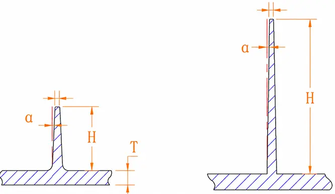
Taller ribs can theoretically provide greater bending stiffness, but increasing rib height also makes both injection molding and mold design more difficult.
A common guideline is: H ≈ 2.5T–3T
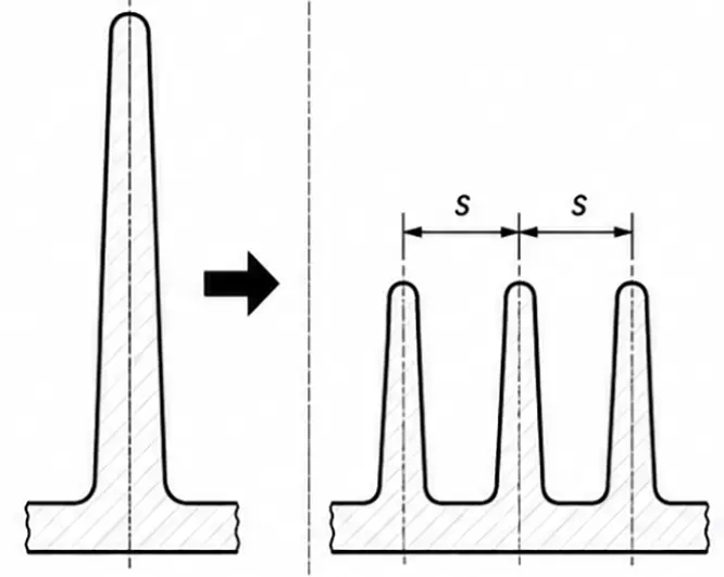
If greater stiffness is required, using several properly distributed ribs is often more practical than designing one excessively tall rib.
3) Rib Draft Angle
Both sides of a rib should have sufficient draft to allow the part to release smoothly from the mold. The draft angle depends on the rib height H, with a typical design range of: 1°–1.5° per side
Keep in mind that draft causes the rib to become progressively thinner from the base toward the top. For taller ribs, the top width should therefore be checked carefully; if it becomes too thin, incomplete filling may occur. Based on our years of experience, the rib width at the top after draft is generally kept at no less than 0.6 mm.
4) Rib Base Radius
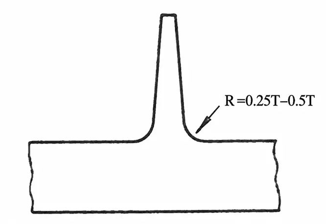
A rib should not meet the main wall with a completely sharp corner. An appropriate radius should be added at the base.
A common starting point is: R = 0.25T–0.5T
The radius allows loads to transfer more smoothly from the rib into the main wall, reducing stress concentration at the base and lowering the risk of cracking.
However, a larger radius is not always better. An excessive radius significantly increases the cross-sectional area at the rib base, creating another locally thick section that can worsen sink marks and uneven cooling.
5) Rib Spacing
When multiple ribs are used, they should not be packed too closely together. A common guideline is to keep the spacing between ribs at least: Around 2T
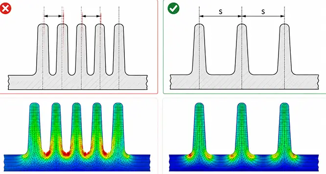
If ribs are spaced too closely, their base regions can interact and create areas of concentrated material. Closely spaced ribs also leave less mold steel between features, which can make mold machining, cooling, and venting more difficult.
2. Rib Layout Design
Even when the rib dimensions are correct, the overall structural design may still be ineffective. Where ribs are placed and how they are oriented can have a direct impact on how much reinforcement they actually provide.
1) Reinforce Structurally Weak Areas First
Ribs should be placed first in areas that are prone to bending, carry loads, or require additional support.
For example, a large flat panel can easily flex under external force. Adding ribs along the primary load-bearing areas can improve bending stiffness. Around local mounting points, joints, or screw bosses, ribs can also help transfer concentrated loads into a larger portion of the main structure.
2) Choose the Right Rib Layout
The rib arrangement should reflect how the part is loaded.
① For parts that mainly experience bending in one direction, parallel ribs can be used. However, parallel ribs should not be packed too closely simply to gain more stiffness; rib spacing has already been discussed in the previous section.
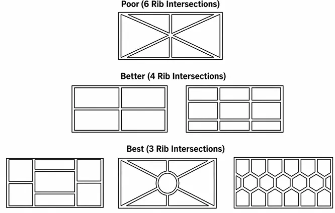
② When stiffness is needed in multiple directions, crossed or grid-style ribs can be used. Where several ribs intersect, avoid having too many ribs converge at a single point.
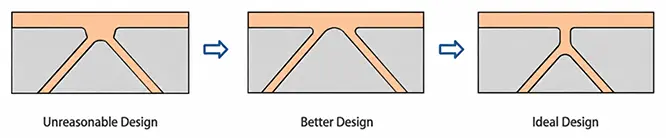
③ When diagonal ribs connect to an outer wall, it is generally better to merge them first before connecting them to the wall, helping reduce local material buildup and sink marks.
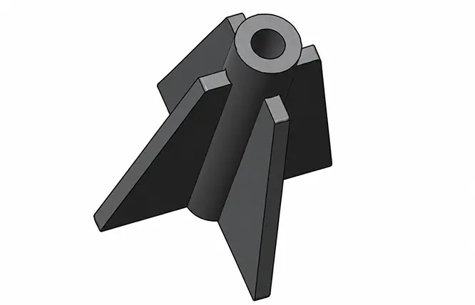
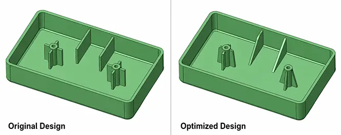
④ For a boss that requires support in multiple directions, radial ribs can be arranged around it to improve lateral stability.
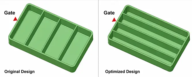
3) Consider Melt Flow Direction
Ribs are preferably arranged parallel to the main melt-flow direction because flow across ribs can split or obstruct the melt path, potentially causing trapped air or restricted flow. Restricted flow may increase internal stress and the risk of short shots.
If a rib does not connect to an inner wall, avoid a sharp right-angle termination at the rib end. During injection, such geometry can easily trap air near the end of the rib. A rounded or chamfered transition helps the melt fill the area more smoothly.
3. How Different Plastics Affect Rib Design
Different plastics have different molding shrinkage rates, which directly affect the risk of sink marks and warpage around rib bases. The following data can be used as a design reference:
| Material | Typical Molding Shrinkage | Recommended Nominal Wall Thickness | Rib Design Considerations |
| ABS | Approx. 0.5%–0.8% | 1.14–3.56 mm | Relatively low shrinkage; conventional rib ratios can be used as a starting point, but thick ribs should still be avoided behind cosmetic surfaces |
| PC | Approx. 0.4%–0.8% | 1.02–3.81 mm | Relatively low shrinkage, but high melt viscosity means deep, thin ribs may be more difficult to fill |
| PP | Approx. 1.3%–2.0% | 0.89–3.81 mm | More noticeable shrinkage; rib thickness should be controlled carefully and the layout kept reasonably uniform |
| PA (Nylon) | Approx. 0.7%–1.5% | 0.76–2.92 mm | Consider shrinkage, moisture absorption, and the effect of local thickness on dimensional stability |
| POM | Approx. 0.4%–2.2% | 0.76–3.05 mm | Shrinkage varies significantly by grade; avoid thick ribs and material buildup around rib bases |
The actual shrinkage rate and suitable wall thickness of the same plastic can vary with the specific grade, fillers, flow length, and molding conditions. Rib thickness should still generally be determined in relation to the nominal wall thickness T.
4. Rib Design Case Study — Preventing Sink Marks
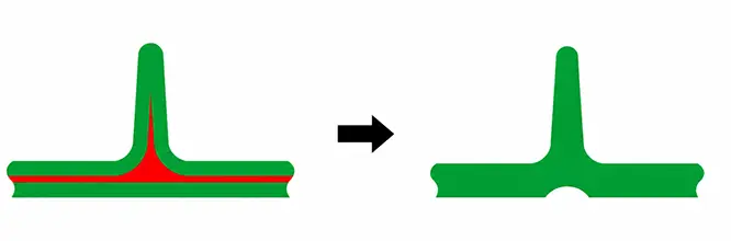
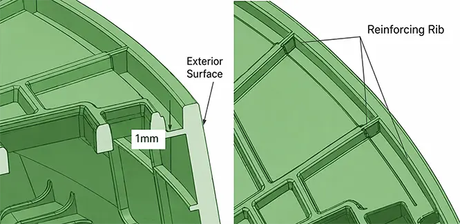
For some ribs that connect both an outer wall and an internal structure, the rib thickness cannot simply be reduced because sufficient internal strength must still be maintained. In this case, sink marks may appear on the cosmetic outer surface. How can this be addressed?
There are two approaches:
Method 1: Reduce the rib thickness only in the section that connects to the outer wall while keeping the rest of the rib at its original thickness. This method is suitable when reducing the rib thickness does not change the mold-release direction, as shown below.
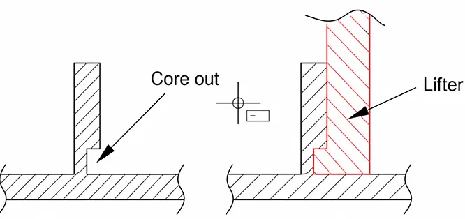
Method 2: If reducing the rib thickness changes the required mold-release direction, use a lifter or slide at the rib base, as shown below, so the section connecting to the outer wall can still be made thinner.
FAQ
Q1: Do more ribs always make a part stronger?
Not necessarily. Too many ribs increase material usage and molding complexity and may also increase the risk of warpage. Rib placement should be based on the actual load requirements of the part.
Q2: Can ribs replace increased wall thickness?
In many cases, yes. Compared with simply increasing the nominal wall thickness, properly designed ribs can improve stiffness with less material while reducing the risk of sink marks caused by thick sections.
Q3: How do you know whether a part has enough ribs?
For simple parts, the number of ribs can be estimated based on experience and the locations of applied loads. For parts with higher load requirements or more complex structures, FEA is recommended for validation.
Q4: Do ribs increase injection mold cost?
They can. Complex, deep, narrow, or numerous ribs can increase the difficulty of mold machining, venting, and even polishing.
Q5: Can ribs still be added after the mold has been completed?
Yes, but the mold core usually needs to be modified. How easy the modification is depends on the rib location, depth, and the existing mold structure.