

In plastic injection mold design, the primary function of the cooling system is to control mold temperature. It directly affects injection cycle time (efficiency) and part deformation (quality). When developing a cooling solution, both sales and design teams should focus on the following key points:
1. Matching Cooling Channel Layout with Product Structure
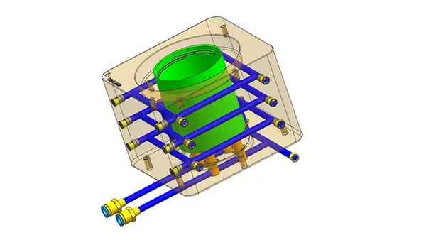
Conformal cooling: For complex surfaces or deep cavity parts, traditional straight-line cooling channels are far from the cavity, resulting in uneven cooling. Ideally, the cooling channel should follow the contour of the part surface. However, this significantly increases machining cost and must be balanced during quotation.
Avoid critical components: Cooling channels must avoid ejector pins, screws, sliders, lifters, and other moving components. Adequate safety distance should be maintained to prevent leakage caused by scale buildup or corrosion over time, which can affect mold life.
2. Cooling Efficiency and Uniformity
“Sandwich” cooling: Cooling strength between the moving side and fixed side must be balanced. The moving side (ejection side) typically has poorer heat dissipation. For parts requiring high flatness, cooling on the moving side often needs to be enhanced to prevent sticking or warpage after mold opening.
Balanced temperature field: Cooling channels should be evenly distributed around the cavity at equal distances to avoid localized overheating or overcooling. The temperature difference between inlet and outlet should be controlled within 2–3°C to prevent dimensional instability or batch color variation.
Priority cooling for critical areas: Thicker sections (such as rib bases and bosses) are heat concentration zones. Independent cooling channels with adjustable flow should be applied; otherwise, defects such as sink marks or internal voids may occur.

3. Relationship Between Cooling Design and Process Parameters
Turbulent flow principle: Cooling channels should be designed to maintain turbulent flow rather than laminar flow to maximize heat transfer efficiency. This requires proper control of channel diameter (typically Φ8–Φ12 mm) and flow rate. Excessive channel length or too many bends will reduce actual flow velocity and cooling performance.
Sealing and maintenance: Cooling connections should be located on the non-operating side of the mold whenever possible to avoid interfering with production. Adequate sealing space must be reserved to prevent high-pressure leakage. In areas with hard water, dead ends and very narrow channels should be avoided to reduce scale buildup and ensure ease of cleaning.
4. Balance Between Cost and Manufacturability
Machining feasibility: Deep-hole drilling must consider tool length limitations and deflection risk. Designing overly long or complex angled channels for ideal cooling may lead to drilling failure and increased cost.
Plugging and sealing risk: The number of cross-drilled channels requiring plugs should be minimized. Each additional plug introduces a potential leakage point and increases assembly and maintenance cost.
In summary, the essence of cooling system design is a balance between cycle time and part quality. Poor design will either extend cycle time to maintain quality or sacrifice part flatness and increase defect rates to maintain efficiency.
At the early stage of a project, mold flow analysis is recommended to validate cooling performance, especially for high-gloss surfaces, glass-filled materials, or complex structures, to avoid costly mold modifications later.
Based on the previous discussion of cooling design and quotation strategy, the following three cases illustrate efficiency improvement, quality issues, and quotation trade-offs.
Case 1: Conformal Cooling Cuts Cycle Time (Efficiency)
Product: Cosmetic case housing (PET material), with uneven wall thickness (thicker hinge area) and high-gloss surface requirement.
Initial solution: Conventional straight-line cooling channels. Due to the deep cavity, cooling channels were far from the cavity, resulting in uneven cooling. The injection cycle was 35 seconds, and the hinge area required slow injection to avoid sink marks, leading to inconsistent gloss.
Issue: Estimated order volume was 5 million units. With a 35-second cycle, daily output per cavity was only about 2,000 parts, leaving almost no profit at the target price.
Improvement: Conformal cooling inserts produced by 3D printing were adopted to closely follow the part contour, especially improving cooling at the hinge area.
Result: Cooling time was reduced from 22 seconds to 9 seconds, and overall cycle efficiency improved by approximately 50%.
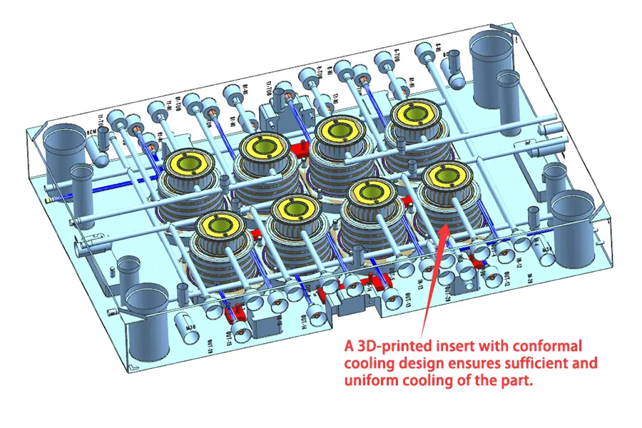

Insight: Although mold cost increased by 30%, the improved efficiency reduced unit cost and recovered the additional investment within two months. For such projects, mold cost should be evaluated based on ROI rather than lowest price.
Case 2: Poor Cooling Design Causes Internal Surface Scratches
Product: Decorative adhesive gun tube (PP material) with smooth internal surface requirement.
Issue: After trial molding, scratches appeared on the inner surface. Process adjustments (mold temperature, injection speed, holding pressure) could not eliminate the defect.
Root cause: The cooling layout in the slider was improperly designed. Cooling channels were connected in series across multiple cavities (8 cavities). As water flowed from the first to the last cavity, temperature gradually increased due to heat absorption, resulting in uneven mold temperature and internal scratches.
Solution: Cooling channels were redesigned so that each cavity had an independent circuit, keeping temperature variation within 3°C. Copper tubes or baffles were added to separate the circuits. The modification increased cost and lead time.
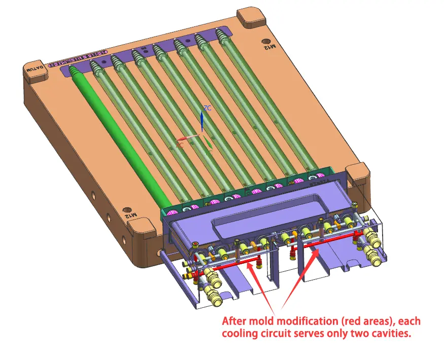

Insight: Such issues are often misdiagnosed as material or machine problems during trial. For cosmetic parts with complex geometry, mold flow analysis should be included in quotation, and responsibility for redesign due to cooling issues should be clearly defined.
Conclusion
The underlying logic of these cases is consistent:
- Cooling is a critical factor—it determines both product quality and production efficiency. Neglecting it during design will lead to higher costs and delays later.
- Quotation should be dynamic—mold cost and part price are interrelated. Providing different combinations for prototyping and mass production stages can improve competitiveness and support long-term cooperation.