


When designing any part for injection molding, it is important to consider the shrinkage and contraction rate of the material and the associated geometry of the component. Plastic shrinkage is the dimensional change that occurs in a molded part as it cools after injection. Most of the part shrinkage occurs while still within the molding tool during the cooling stage, but a small amount of shrinkage occurs after ejection, as the part continues to cool (especially for Delrin or POM).
Upon ejection, the majority of the excess heat has been already dissipated and the majority of shrinkage has occurred. The part may continue to shrink very slightly for several hours or even days until the temperature and moisture content stabilize to match that of the surrounding environment. As a result, to maintain consistency and suitable part stabilization, the dimensional inspection should wait at least a day after part ejection.
Plastic injection molded part shrinkage units are expressed as thousandths of an inch per linear inch (0.00X /in/in). Typical shrink rates vary between 0.001/in/in and .020/in/in – depending on material, wall thickness, cooling rates and other variables – with the average being around 0.006/in/in.

Compensating in the Model vs. in the Mold
When calculating shrinkage, the tooling engineer simply scales the mold tooling by 1.00X. In pre-CAD days, the engineer would compensate for shrinkage by enlarging the part by simply multiplying every number on the drawing by 1.00X. At ICOMold, the shrinkage compensation takes place at the mold building stage, so the stabilized part dimensions should align with the CAD model specs and part prints. In other words, we compensate for shrinkage so that the part specs meet the model.
Plastic injection molding shrinkage varies with wall thickness also. The material supplier will usually provide a material data sheet that specifies a shrinking range for the material. e.g. 0.005-0.007/in/in for a 0.100 inch wall thickness. In turn, if the wall was 0.100″ during validation and inspection, the parts would be expected to have a shrink average of 0.006″ along those walls. When developing parts with tight tolerances, it is absolutely critical to factor in the shrink rate at the tooling design stage, to ensure that the final parts meet the model specs.

Fine Tuning Shrinkage Compensation
The molder can fine tune the shrinkage of the parts by adjusting the density of the material, i.e. how hard they pack it out, and the length of the cooling period within the mold. If the part is large, tolerances are critical, or a new or exotic material is being used, then we would always recommend performing test shots prior kicking off production.
Many injection molders have a huge rack of obsolete tools. A great solution would be to reach out to the molding facility and find one that makes a part somewhat similar in size, shape and wall thickness to your part. For a small fee the molder will shoot your desired resin into the mold and then use the parts to calculate a precise shrinkage for your material in a similar profile to your product. This solution is highly beneficial and certainly worth taking the extra time and investment to perform it, as the cost is orders of magnitude cheaper than reworking or scrapping a tool due to parts being out of tolerance.

Asymmetrical Shrinkage
Because of the complex chemical composition of polymers, different plastic materials behave differently than each other. It is therefore critical to review a material’s data sheet prior tooling development. Another layer of complexity is added for materials with asymmetrical shrinkage characteristics. These are plastics that have different shrinkage in one direction than another.
For example, polymers filled with long glass fibers will shrink more in the cross (transverse) direction than the longitudinal (flow) direction. This poses an interesting dilemma for the mold designer. The material supplier documentation will state there is a different shrink rate in the X axis than in the Y. It is not such a problem for long straight parts like popsicle sticks or rulers, but can be challenging for parts with complex geometries.
If the part is complex, like with holes and flow fronts meeting at different angles and running different directions at different places in the part, it is impossible to calculate and model with accuracy. The time and cost to model the result would be an expensive and unnecessary study, even if it could be performed to a desired level of confidence/reliability.
For example, the complexity goes down to even simple geometries like round holes. They would become elliptical in the tool due to the molten plastic flow and the subsequent shrinkage relative to the direction of the fibers in the material. Standard components like core pins could not be used.
An approximation of the mold shrinkage is applied to the entire part by averaging the shrinkage between longitudinal and cross-shrinkage. This enables a good first-round approximation and requires all parties to sign off on the approach due to the possible variability in the results. Then critical features are altered or added after first shots, based on an analysis of the material flow and shrinkage.
The bottom line is, try to avoid asymmetrical shrinkage resins if close tolerances are highly critical.

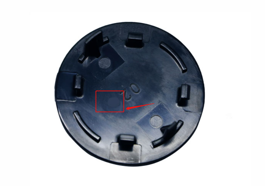
Causes of plastic injection molding shrinkage marks
There may be one or more reasons for forming shrinkage marks during plastic injection molding, including processing methods, component geometry, material selection, and plastic mold design. The geometry and material selection are often determined by the raw material supplier and are not easily changed. However, there are many factors about mold design on the part of the mold manufacturer that may affect the shrinkage of plastic injection processing. Cooling runner design gate type and gate size may produce a variety of effects. For example, a small gate such as a pipe gate cools much faster than a tapered gate. Premature cooling at the gate reduces the filling time in the cavity and increases the chance of shrinkage marks. For molding workers, adjusting processing conditions is a way to solve the shrinkage problem of plastic processing. Filling pressure and time significantly affect shrinkage. After the parts are filled, the excess material continues to fill the cavity to compensate for the material shrinkage. If the filling stage is too short, the contraction will be intensified and more or larger contraction marks will be produced.
RJC was established in 2002 and engaged in engineering service and technical manufacturing, such as rapid prototyping, mold manufacturing, injection molding, and CNC machining.CNC machining.RJC would be a good vendor choice.
click :https://rjcmold.com/contact-us/
Send inqury.