In plastic manufacturing, small design errors can lead to expensive structural failures. To avoid this, engineers use Mold Flow Analysis. It is a simulation process that predicts how molten plastic will behave inside a mold.
A special software is used to model this infection model. The purpose is to make sure that parts are perfect before you cut the metal.

What Is Mold Flow Analysis?
Definition of Mold Flow Analysis
Mold Flow Analysis is a digital simulation that mimics the injection molding process. Injection molding companies use specialized software to visualize how liquid plastic fills a cavity before they ever cut a single piece of steel. This predictive step allows the customers to see the future of their production run on a computer screen.
Role of Mold Flow Analysis in Injection Mold Design
MFA acts as a bridge between a 3D design and a physical product. In the beginning, designers might create parts that look great but are impossible to manufacture. This analysis identifies those “un-moldable” features early. It helps you decide the best way to design the mold to handle the heat and pressure of real-world machines.
Important Aspects Analyzed in Mold Flow Analysis
In mold flow analysis, injection molding experts will check the melt temperature, the injection pressure, and the fill time.
First, of course, they will check the melt temperature. If the plastic gets too cold, it will stop flowing; if it gets too hot, it might burn! Next, you can see how the plastic will shrink as it cools. By checking these factors early, it will ensure the plastic stays at the right consistency.
How Mold Flow Analysis Works
Mold Flow Simulation Process Explained
First, upload your 3D CAD model into the software. Then, select the specific plastic resin you plan to use. The software breaks the part into thousands of tiny shapes called a mesh. Consequently, the computer calculates the physics of flow for every tiny section to create a complete picture.
Important Parameters Evaluated During Simulation
During the run, the software looks at shear rate and viscosity. Monitor the clamping force required to keep the mold shut. According to industry data, improper pressure calculations are a leading cause of tool fatigue. If the pressure is too high, it might break your injection molding machine.
Understanding Mold Flow Analysis Results

After the simulation finishes, you’ll want to look at the color-coded maps. Red areas usually mean high heat or pressure, while blue areas are cooler. You can then use these visual cues to spot short shots where the plastic does not reach the end of the cavity.
When to Use Mold Flow Analysis
Design and Geometry Complexity
If the part has variable wall thicknesses or very thin ribs, always run an analysis. Complex shapes often cause the plastic to “hesitate” or stall. This leads to weak spots. It just means that the more complex the part, the more digital tests will be required.
Material and Production Considerations
You should use MFA when working with expensive or fiber-filled resins. These materials are tricky because the fibers must align correctly for strength. On the other hand, for high-volume production, even a small error in cycle time can cost thousands of dollars over a year.
Situations Where Mold Flow Analysis Is Optional
Sometimes a simpler approach is better. If you are making a basic, flat part with a common material like Polypropylene, you might skip the full analysis. This often just happens when the mold design is “tried and true” from previous projects.
Important Applications of Mold Flow Analysis
Gate Location and Flow Optimization

The “gate” is where the plastic enters the mold. To begin, find the optimal gate location. If the gate is in the wrong spot, the plastic might not fill the mold evenly. MFA shows exactly where to place the entry point to get a balanced flow.
Weld Line, Air Trap, and Defect Prediction
When two flows of plastic meet, they form a weld line. These lines are often weak and ugly. Note that always keep weld lines away from visible or high-stress areas. The software also finds air traps where gas gets stuck, which can cause burn marks on your plastic.
Warpage, Shrinkage, and Cooling Analysis
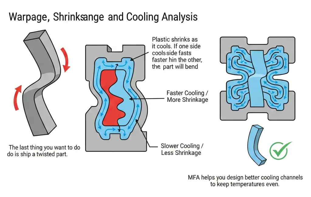
Start from analyzing the warpage. Plastic shrinks as it cools. If one side cools faster than the other, the part will bend. MFA helps you design better cooling channels to keep temperatures even.
Case Study: Solving Warpage in Automotive Panels
At our factory, we found that a large automotive interior panel was consistently failing quality checks due to a 3mm bow in the center. Originally, the team thought the material was the problem. We ran a Mold Flow Analysis and discovered the cooling lines were uneven. After that, we rearranged the water circuits based on the simulation results. Consequently, the warpage dropped to under 0.5mm, saving the client over $15,000 in potential scrap costs.
Popular Mold Flow Analysis Software
Leading Commercial Mold Flow Analysis Tools
Autodesk Moldflow is a helpful and widely used tool in the industry. Moldex3D is another top choice, known for its deep 3D analysis capabilities. Many engineers also use SolidWorks Plastics because it integrates directly with their design software.
Differences Between Mold Flow Simulation Software
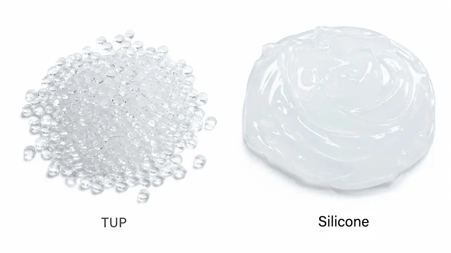
SimForm is very accurate for fast, cloud-based cooling checks for plastic. On the other hand, SigmaSoft is good at Virtual Molding. You can easily solve complex problems with rubber, and silicone. By choosing the right software, save both time and money.
How to Choose the Right Mold Software
First, of course, budget should be the first priority. Premium commercial tools can be very expensive. Your next step should be your team’s skill level. For example, some software is plug and play, but other versions require a dedicated engineer to interpret the data correctly.
Step-by-Step Guide to Conducting Mold Flow Analysis
Preparing the Design and Material Data
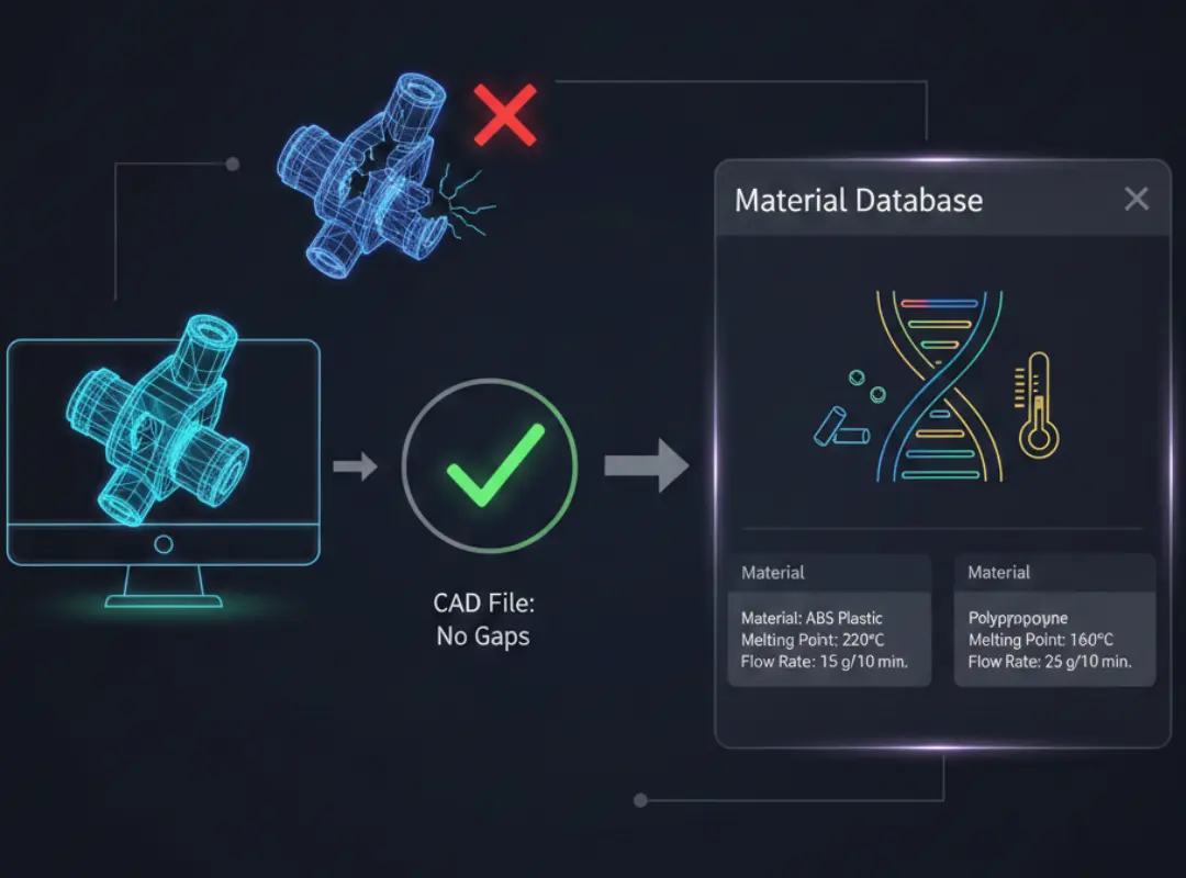
Ensure your CAD file is “clean” with no gaps. Then, select your material from the software’s material database. This database has the “DNA” of the plastic. For example, it has a melting point and flow rate.
Setting Up and Running the Simulation
Set your processing conditions like melt temperature and injection speed. Define the mold temperature as well. After that, press “run”. According to the complexity, this will happen in a few minutes or a few hours.
Interpreting Results and Optimizing the Design
Once the simulation is done, check the filling pattern. If you see issues, modify the wall thickness or move the gate. After a few adjustments, run the simulation again. This iterative process is the best way to do this correctly.
Common Issues Detected by Mold Flow Analysis
Filling and Flow-Related Defects
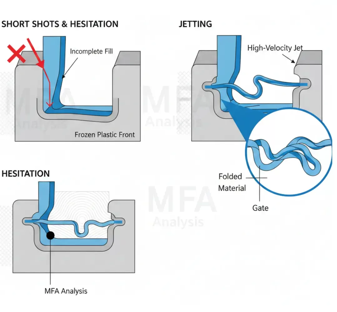
MFA is great for spotting short shots and hesitation. This often occurs when the plastic freezes before reaching the end. You can also see jetting, where the plastic goes into the cavity instead of filling it smoothly.
Thermal and Pressure-Related Issues
If your injection pressure is too high, you might get a flash, where plastic leaks out of the mold. The analysis also detects thermal degradation. This happens when the plastic stays too hot for too long and begins to chemically break down.
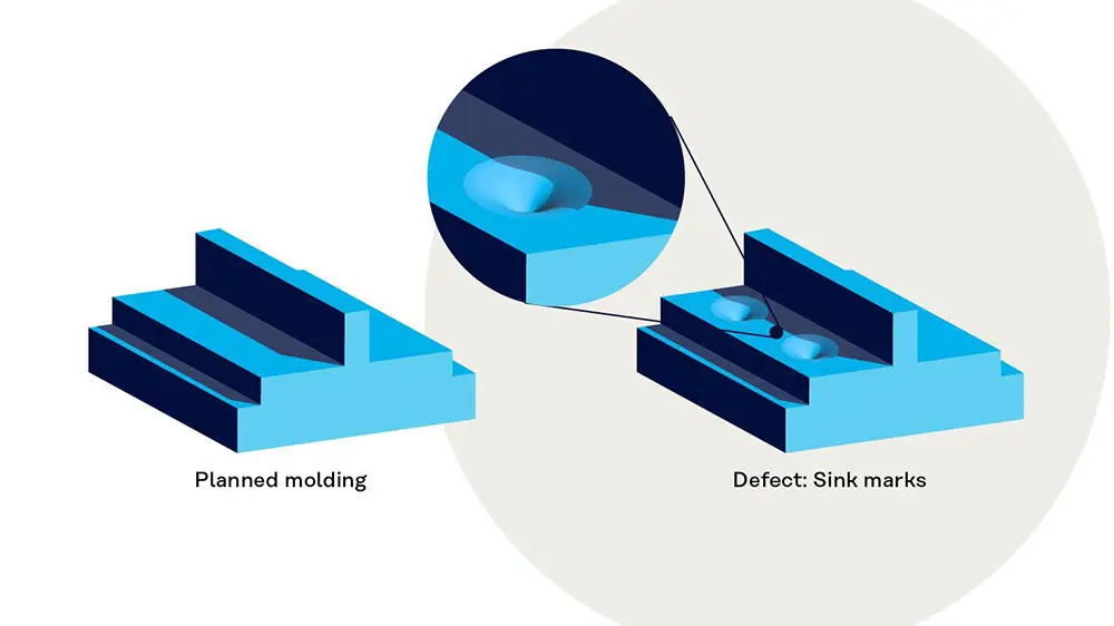
Dimensional and Structural Problems

You should be able to predict sink marks in thick sections. These are small craters on the surface. Furthermore, the analysis helps you see if the part will meet tight tolerances once it is fully cooled and ejected.
Best Practices for Mold Flow Analysis
Timing and Data Accuracy
Just make sure you do the analysis before you start building the custom injection mold. Until then, your design is just a theory. You also need accurate data for the material. No way to know if the results are right if the input data is wrong.
Iterative Optimization Approach
Do not settle for the first result. You’ll want to test different gate sizes and cooling layouts. Comparison is a helpful way to find the most efficient cycle time. This will help you save money on every single part you produce.
Team Collaboration and Documentation
Communication is very important just like engineering. By sharing your reports with the team, everyone knows exactly how to set up the machines. Keeping these records helps the plastic parts manufacturers to get better at making high-quality products every single day!