In the injection molding process, the design of the gating system is a critical factor determining product quality, production efficiency, and cost. The choice of gating method directly impacts product appearance, dimensional stability, internal stress distribution, and material utilization.
This article compiles seven mainstream plastic mold gating methods, providing an in-depth comparison based on selection criteria, advantages, disadvantages, and applicable scenarios to help you make the optimal decision during the early stages of mold development.
I. What is a Gating System?
The gating system refers to the channel through which molten plastic travels from the injection molding machine nozzle to the mold cavity. The gate is the terminal part of this system and is the core node controlling plastic flow rate, cooling time, and final molding quality. An incorrect gate design can lead to issues such as weld lines, gas marks, warpage, and even difficulty in demolding.
II. Detailed Explanation of Mainstream Gating Methods
Below are the seven most commonly used gating methods in the industry, with their characteristics analyzed one by one.
1. Direct Gate (Sprue Gate)
Structural Characteristics: Plastic flows directly from the main sprue into the cavity, typically located on the top or center of the product.
Selection Criteria: Suitable for single-cavity molds, large deep-cavity products, or parts with high strength requirements (e.g., housings, frames).
Advantages: Low flow resistance, short molding cycle; direct transfer of packing pressure reduces sink marks.
Disadvantages: Obvious gate residue requires post-processing removal; prone to high internal stress at the gate location.
2. Edge Gate (Side Gate)
Structural Characteristics: The gate is located on the side of the product, usually on the parting surface.
Selection Criteria: The most common gating method, suitable for most small to medium-sized flat or housing products.
Advantages: Easy to process, low mold cost; flexible gate positioning facilitates balanced filling in multi-cavity molds.
Disadvantages: Leaves a noticeable mark on the product side, affecting aesthetics; not suitable for transparent or cosmetic parts.
3. Pinpoint Gate (Pin Gate)
Structural Characteristics: Very small gate diameter (typically 0.5-1.5 mm), flexible gate placement, commonly used with three-plate molds.
Selection Criteria: Suitable for small precision parts requiring automatic demolding and high appearance quality (e.g., connectors, gears, thin-walled parts).
Advantages: Gate breaks automatically, enabling automated production; minimal gate mark, nearly invisible.
Disadvantages: Significant pressure loss, unsuitable for thick-walled parts; sensitive to injection molding process, prone to jetting.
4. Submarine Gate (Tunnel Gate)
Structural Characteristics: The gate is hidden below the parting surface or feeds through an ejector pin, injecting material from the inside or side of the product.
Selection Criteria: Suitable for products where external gate marks are unacceptable or for fully automated production.
Advantages: Gate is automatically cut during ejection, eliminating manual trimming; no visible mark, enhancing product perceived quality.
Disadvantages: Complex mold structure, high processing difficulty; gate placement is restricted, not suitable for brittle materials.
5. Fan Gate
Structural Characteristics: The gate width gradually expands, entering the cavity in a fan shape.
Selection Criteria: Suitable for large flat plates, thin-walled parts, or transparent parts (e.g., panels, lamp covers) to reduce flow marks and jetting.
Advantages: Melt front advances linearly, good venting, reduces warpage; eliminates weld lines.
Disadvantages: Large gate area, difficult to remove; higher material waste.
6. Film Gate (Edge Film Gate)
Structural Characteristics: Material enters through a narrow, film-like channel uniformly into the cavity.
Selection Criteria: Used for elongated products with extremely strict warpage requirements or poor flowability.
Advantages: Uniform melt flow, significantly reduces internal stress; suitable for high-precision optical parts or engineering plastics.
Disadvantages: Complex mold structure, high processing cost; gate removal is cumbersome.
7. Hot Runner (Valve Gate / Needle Valve)
Structural Characteristics: Not a traditional “gate,” but part of a runnerless system, feeding directly through a hot nozzle.
Selection Criteria: High-volume automated production, expensive materials, or applications requiring multi-point gate control (e.g., large automotive parts, precision gears).
Advantages: No runner waste, saves raw material; precise injection pressure control, high yield.
Disadvantages: High mold cost, complex maintenance; demanding temperature control system, difficult color changes.
III. Gating Method Comparison Table (Core Reference)
| Gating Method | Gate Mark | Automation Level | Mold Cost | Suitable Materials | Typical Applications |
| Direct Gate | Obvious, post-processing needed | Low | Low | General Plastics | Trash cans, large housings |
| Edge Gate | Noticeable, easy to trim | Medium | Low | General Plastics | Toys, appliance housings |
| Pinpoint Gate | Tiny, nearly invisible | High | Medium-High | Good flow (ABS/PP/PA) | Connectors, gears, precision parts |
| Submarine Gate | Hidden, no external mark | High | Medium-High | Good toughness (PP/PE) | Cosmetic caps, internal structures |
| Fan Gate | Obvious, needs trimming | Medium | Medium | Poor flow (PC/PMMA) | Transparent panels, large flat plates |
| Film Gate | Slight mark | Medium | High | Engineering Plastics (PC/ABS) | Long thin-walled parts, optical parts |
| Hot Runner | None or minimal | Very High | Very High | Various Engineering Plastics | Automotive lights, precision medical parts, high-volume parts |
IV. How to Choose a Gating Method? 5 Key Considerations
In practical projects, selecting a gating method often requires balancing the following factors:
- Product Appearance Requirements: If the product has cosmetic surfaces (e.g., automotive interiors, consumer electronics), prioritize pinpoint gates, submarine gates, or hot runners to avoid visible marks.
- Product Structure & Size: For large deep-cavity parts, a direct gate aids filling; for flat large plates, fan or film gates prevent warpage; for thin-walled parts, pinpoint gates combined with high-speed injection are mainstream.
- Material Flowability: For materials with poor flowability (e.g., PC, PMMA) or glass-fiber reinforced materials, fan gates or hot runners are recommended to minimize jetting marks and uneven fiber orientation.
- Production Efficiency & Cost: For high-volume orders, hot runners or submarine gates, despite higher initial costs, save labor for degating and reduce waste, offering better long-term returns. For low-volume trial runs, edge gates are an economical choice.
- Mold Structure & Lifespan: The gate location must avoid mechanisms like ejector pins and sliders. For abrasive materials (e.g., glass-filled), the gate area requires wear-resistant inserts; simpler designs (like edge gates) generally result in longer mold life.
V. Case Study
Case Study 1: Battery Pack Housing – Pinpoint Gate for Mark-Free Appearance
Product Features: Material: PC+ABS (high cosmetic requirement); Dimensions: 180×180×130mm, wall thickness 1.8mm.
Core Challenge: The surface could not show any gate marks and required dimensional stability.
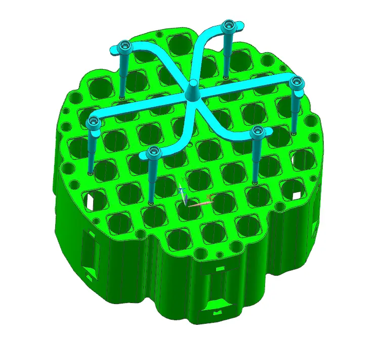
Gating Solution: Adopted a three-plate mold with 6 pinpoint gates symmetrically distributed on the non-cosmetic back surface.
Rationale: Pinpoint gates break automatically, suitable for automation. Gate mark diameter is only 0.6mm, located in internal snap grooves, invisible on the cosmetic surface. 6 gates ensure simultaneous melt front arrival.
Advantages/Disadvantages Comparison: Appearance: Completely invisible marks; Mold Cost: Medium-high for three-plate mold; Cycle Time: Automatic demolding, ~65 seconds; Material Suitability: Requires good flowability for PC.
Production Result: Yield improved from 82% (with edge gate) to 96%, eliminating gate whitening on cosmetic surfaces and enabling fully automated production.
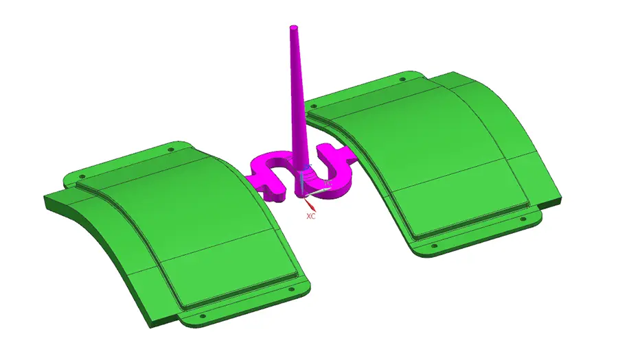
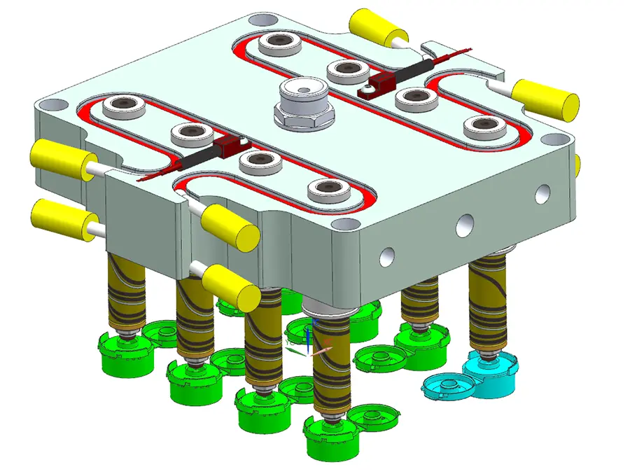
Case Study 2: Charging Gun Body – Submarine Gate + Hot Runner Combination
Product Features: Material: PC + 20% glass fiber; Dimensions: Length 250mm, Width 160mm, Thickness 60mm.
Core Challenge: Gate could not be on the cosmetic surface, and the glass-filled material was abrasive to the gate.
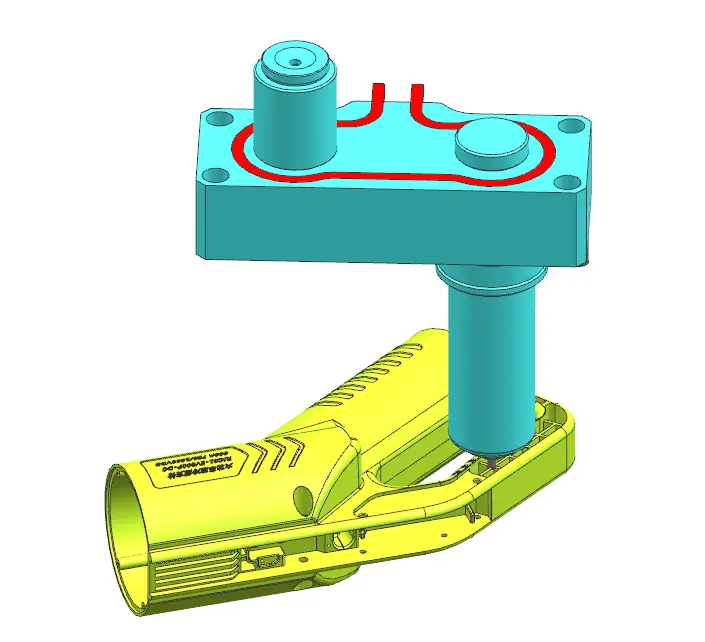
The gate mark is hidden inside the assembly slot, completely invisible.
Gating Solution: Utilized a hot runner system with a submarine gate, hidden within the product’s assembly slot.
Rationale: The submarine gate self-trims during mold opening, eliminating post-processing. The hot runner maintains melt temperature stability, preventing premature freezing of the glass-filled material. The gate is located on a non-functional surface, not affecting assembly or appearance.
Advantages/Disadvantages Comparison: Appearance: No visible external gate marks; Mold Cost: High due to hot runner + submarine structure; Material Utilization: No runner waste, saving PC+GF material; Mold Life: Required wear-resistant inserts at gate area.
Production Result: Mold life reached 800,000 cycles, per-part material cost reduced by 12%, product met customer requirements with no appearance defects.
Case Study 3: Large Transparent PC Lamp Cover – Fan Gate Solving Flow Marks & Gas Marks
Product Features: Material: PC (polycarbonate, transparent); Dimensions: 150×110×15mm, wall thickness 2.5mm.
Core Challenge: Transparent part could not have flow marks, jetting marks, or bubbles.
The melt front advances linearly without jetting.
Gating Solution: Adopted a fan gate, allowing a smooth transition from one end into the cavity.
Rationale: The fan gate allows the melt front to advance radially, preventing jetting. The wide gate area results in low shear rates, reducing flow marks and stress whitening in PC. Facilitates venting, preventing gas trap burns.
Advantages/Disadvantages Comparison: Appearance: No obvious flow marks, light transmittance met requirements; Mold Cost: Simple processing, moderate cost; Waste Ratio: Large gate area required post-cutting; Material Suitability: Suitable for transparent or poor-flow materials like PC, PMMA.
Production Result: Initial yield was 92% (primary defect was micro-cracks during gate trimming). After switching to laser cutting, yield increased to 97%, becoming the preferred solution for this customer’s transparent parts.
Case Study 4: Multi-Cavity Medical Connector – Hot Runner Valve Gate for Precision & Stability
Product Features: Material: PP; Dimensions: 58×30×15mm, wall thickness 0.9mm.
Core Challenge: 8 cavities running simultaneously, requiring balanced filling for each cavity and dimensional tolerance of ±0.02mm.
Each valve gate feeds directly onto the inner surface of the product.
Gating Solution: Employed a hot runner valve gate system, with each cavity independently controlled for needle valve opening timing.
Rationale: Valve gates enable sequential injection molding, eliminating weld lines. No runner waste offers significant material savings. Independent cavity control ensures consistent filling across all 8 cavities.
Advantages/Disadvantages Comparison: Dimensional Stability: Met ±0.02mm high precision; Mold Cost: Very high due to hot runner system; Maintenance Complexity: Requires professional temperature control and valve pin maintenance; Application Scenario: High precision, high volume, expensive materials.
Production Result: Total mold investment was approximately ¥180,000 (including hot runner), but per-part material savings reached 20%. With an annual output of 2 million parts, the mold’s premium cost was recovered within 8 months. Product yield remained stable at 98.5%.
VI. Conclusion
There is no absolute “best” gating method, only the “most suitable.” An excellent mold design finds the optimal balance between product function, aesthetic appearance, production cost, and cycle time.
If you are developing a new product or encountering issues like poor filling, warpage, or stress cracking with existing molds, feel free to consult us. With over 20 years of experience in precision mold manufacturing, we provide one-stop solutions from DFM (Design for Manufacturability) analysis to mass production, helping you mitigate risks and shorten time-to-market.
If you would like to read more articles about injection mold components:
What Are Ejector Pins in Injection Molding?
What is a Lifter in Injection Molds?