1. Basic Concept
An ejector pin can be understood simply as a “rod that pushes the part out.” After the mold opens, the ejector plate moves forward, driving the pins to advance and push the plastic part out of the cavity. The pins then retract, and the mold proceeds into the next cycle.
Although it may seem like a finishing step, ejector pins often determine whether a part can be released smoothly, whether surface defects will appear, and whether production cycles remain stable.
2. Types of Ejector Pins in Injection Molding
Different product structures, demolding resistance, and appearance requirements determine which type of ejection component should be used.
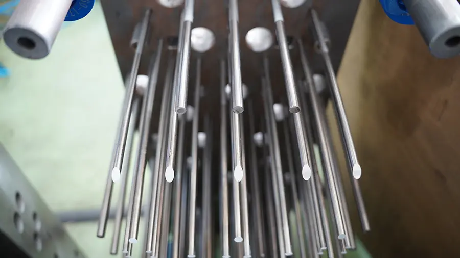
Round Ejector Pins
This is the most common type and works well for most standard parts. It features a simple structure, high standardization, and is easy to machine and maintain. For flat areas or general support zones, round pins are usually sufficient.
Stepped Ejector Pins
These pins have multiple diameters along their working section and shoulder. They are suitable for applications requiring positioning, strength, or localized support. Compared to standard round pins, they perform better in confined spaces where force concentration must be controlled.
Flat Ejector Pins
Used for thin ribs, narrow slots, and flange edges. Round pins often provide too little contact area in these regions, which can lead to whitening or deformation. Flat pins increase the contact surface, allowing force to be distributed more evenly.
Sleeve Ejectors
Sleeves are typically used for bosses, deep holes, or cylindrical features. Instead of applying force at a single point, they support and push the part along its circumference, making them more stable than round pins in these applications.
Strictly speaking, for parts requiring side-action demolding, lifters or similar mechanisms may be used alongside the ejection system, but these are not considered standard ejector pins.
In practical terms, choosing the right ejector type is not about form—it’s about demolding logic. If round pins are forced onto thin ribs or sleeves are avoided for deep bosses, instability is inevitable. The issue is not process settings, but incorrect design decisions from the beginning.
3. Common Materials for Ejector Pins
Material selection is not about “the harder, the better,” but about matching the working conditions. Ejector pins must withstand repeated wear while maintaining enough toughness to prevent breakage, bending, or galling.
SKD61 (Hot Work Tool Steel)
This is the most widely used material. It offers a balanced combination of strength, toughness, and thermal fatigue resistance, making it suitable for high-frequency production molds. Variants from different regions vary in cost and quality.
SKH51 (High-Speed Steel)
This material provides higher hardness and wear resistance, making it suitable for high-precision or high-wear conditions. However, higher hardness also means higher requirements for machining, cost, and operating conditions.
Nitrided Ejector Pins
These are typically made from tool steel with a nitrided surface layer. This improves surface hardness and wear resistance while maintaining core toughness, making them suitable for production molds requiring both durability and stability.
S136 Stainless Steel Ejector Pins
These are valuable in environments with higher corrosion risk or less controlled maintenance conditions. They offer strong corrosion resistance but are not universally superior to tool steel.
Coated Ejector Pins
Some pins feature special coatings or surface treatments to reduce friction, improve wear resistance, and minimize galling. These are suitable for applications requiring consistent performance over long production runs.
In one case involving cosmetic parts, initial efforts focused on adjusting process parameters to reduce ejector marks. Later analysis revealed the real issue was the conservative choice of pin material and surface condition. As the pins wore down, friction increased, making force distribution harder to control. What appeared to be process instability was actually a component selection problem.
4. How Do Ejector Pins Work?
The process itself is straightforward, but each step is critical.
Molten plastic first fills the cavity and cools. As it shrinks, the part typically grips the core more tightly. The mold then opens, and the part usually remains on the core side. The ejection system activates, pushing the pins forward to apply force at specific locations, separating the part from the core. After ejection, the pins retract, the mold closes, and the next cycle begins.
A well-designed ejection system should aim to:
- Place ejector pins in structurally strong areas
- Distribute force as evenly as possible to avoid localized overload
- Match the number, diameter, and layout of pins to demolding resistance
- Coordinate ejection timing with cooling, avoiding premature ejection
Although the principle seems simple, it is not just about pushing—it is about control. When controlled properly, parts release smoothly. When not, ejector pins can become a source of defects.
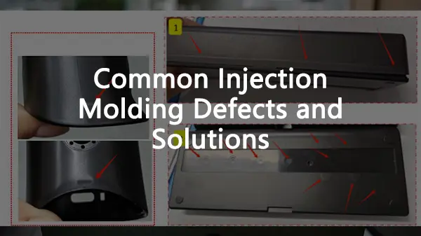
5. Causes and Solutions for Ejector Marks
Ejector marks are one of the most common—and most frequently misunderstood—issues in injection molding. Many people immediately adjust pressure, temperature, or ejection speed, often making the situation worse. This is because ejector marks are rarely caused by processing alone; they are usually the result of combined factors involving design, tooling, and process conditions.
Common Causes
Insufficient number or diameter of pins
Excessive force at a single point leads to stress concentration, causing whitening, dents, or raised marks.
Poor pin placement
Marks are more visible and harder to correct when pins are located on thin walls, slopes, textured surfaces, or cosmetic areas.
Insufficient draft angle
If the part grips the mold too tightly, greater force is required, resulting in more pronounced marks.
Uneven cooling or premature ejection
If the part is ejected before it stabilizes, localized stress can cause whitening, deformation, or even cracking.
Material or surface mismatch
Worn pin surfaces increase friction, leading to unstable ejection forces and worsening marks.
Solutions
Solving ejector mark issues requires the right sequence. The focus should be on root causes, not just parameter adjustments.
First, reduce demolding resistance
Check draft angles, part sticking conditions, and mold venting and cooling. Without addressing resistance, ejector marks will persist.
Second, optimize the ejection design
Increase the number of pins, adjust their placement, and enlarge contact areas. Consider using flat pins, sleeves, or alternative methods when necessary. The goal is to distribute force rather than concentrate it.
Third, adjust process parameters
Only after design and ejection are optimized should cooling time, ejection speed, and timing be fine-tuned.
In most cases, ejector mark issues are not caused by poor machine tuning. They originate during the design phase and only become visible during ejection.
6. FAQs
1) Do ejector pins always leave marks?
Not completely avoidable, but they can be controlled. The goal is not absolute invisibility, but keeping marks in non-cosmetic areas or within acceptable limits.
2) Are more ejector pins always better?
No. Too few cause excessive localized force, while too many increase machining complexity, mark control difficulty, and maintenance costs. Proper distribution matters more than quantity.
3) When should sleeve ejectors be used?
When parts include bosses, deep holes, or cylindrical features, or when uniform circumferential ejection is required.
4) What is the most effective way to eliminate ejector marks?
Reduce demolding resistance first, then optimize the ejection design, and finally adjust process parameters. Simply increasing ejection force usually worsens the problem.
5) Is harder material always better for ejector pins?
No. Higher hardness may improve wear resistance, but it does not guarantee better toughness, corrosion resistance, or overall suitability. Material selection must match the application.
6) Can ejector pins be used on cosmetic parts?
Yes, but with stricter control. Pin placement, quantity, contact area, and mark management must be carefully considered during the design stage rather than adjusted later.