For mass-produced consumer robots and most service robots, PC/ABS should be the primary material choice. Depending on operating conditions, ABS, glass-fiber–reinforced PA (PA+GF), or PBT can then be evaluated as alternatives.
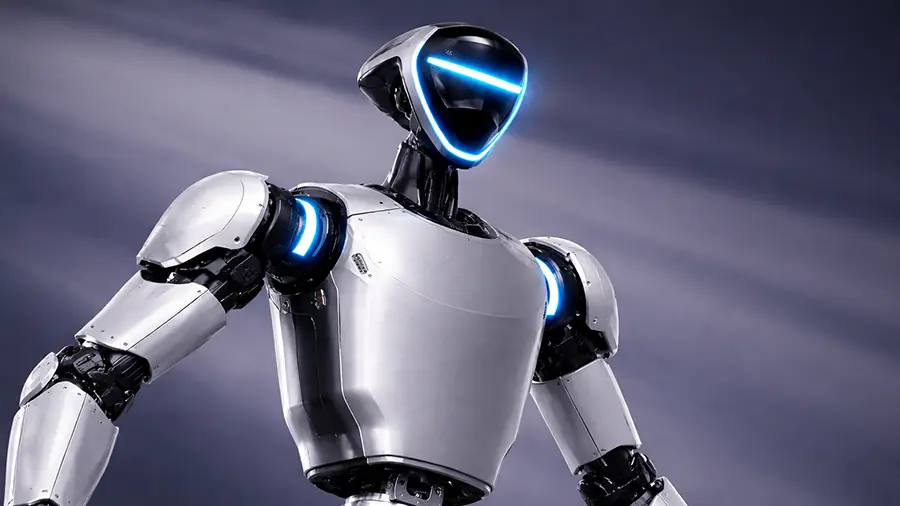
A robot enclosure is not merely a cosmetic part. It is a structural system that must simultaneously withstand drop impact, ensure screw boss durability, isolate heat sources, manage EMI, and accommodate assembly tolerances. If the material choice is wrong, downstream fixes—such as adding ribs, adhesives, or surface coatings—usually only postpone failure rather than eliminate it.
Selecting Robot Enclosure Materials by Application Scenario
1. First Choice for General Mass Production: PC/ABS
If your enclosure must balance strength, toughness, heat resistance, dimensional stability, and consistent appearance, PC/ABS is typically the most reliable compromise. It is particularly well suited for thin-wall designs and complex snap-fit structures, and it offers a relatively forgiving processing window for injection molding.
Many PC/ABS grades demonstrate a strong combination of impact resistance and heat performance in their datasheets. For example, selected PC/ABS grades from SABIC (such as the Cycoloy series) show tensile strength and notched impact values well aligned with enclosure applications and can serve as a useful baseline for material benchmarking (see SABIC Cycoloy XCY630 PC/ABS property datasheet).
When drop conditions, assembly methods, and heat-source layouts are not yet fully defined, starting with PC/ABS minimizes the risk of making a fundamentally wrong material decision.
2. Cost-Sensitive, Light-Duty Indoor Use: ABS
ABS offers advantages in cost and surface appearance, making it suitable for indoor, low-temperature-rise, light-load enclosures—especially for large cosmetic covers or decorative panels that contribute little to structural performance.
The issue with ABS is that it often reveals weaknesses under the combined effects of screw bosses, drop impact, and thermal cycling. Common failure modes include micro-cracking at the root of screw bosses and insufficient weld-line strength.
In one project, ABS was selected over PC/ABS for a top cover purely to reduce cost. During prototyping, the difference was barely noticeable. However, after mass production, widespread screw-boss cracking occurred. The rework and inspection costs quickly exceeded the original material savings.
ABS is not unusable—but it should never be used as a gamble against after-sales risk.
3. High Strength, Rigidity, and Fatigue Resistance: Glass-Fiber–Reinforced PA (PA+GF)
When the enclosure must serve a structural role—such as load-bearing joint covers, repeated screw engagement, or long-term vibration and fatigue—PA (nylon) reinforced with glass fiber is often the more reliable choice.

PA+GF provides significantly higher stiffness and screw retention strength. However, these benefits come with trade-offs: dimensional stability is harder to control, as moisture absorption can cause dimensional drift that amplifies assembly tolerance issues. Surface appearance is also more challenging, with visible weld lines, fiber exposure, and a finish that is harder to make “consumer-electronics–grade.”
If you choose PA+GF, the design must acknowledge its nature:
treat it as a structural material, not an appearance material.
4. Improved Heat and Chemical Resistance: PBT (with GF if required)
For areas near motors, driver boards, batteries, or zones exposed to cleaning agents or oils, PBT (optionally reinforced with glass fiber) is often more resistant to long-term degradation than ABS. Issues such as stress cracking and warpage are generally more controllable.
That said, PBT demands stricter mold-temperature control and gate design to maintain stable appearance and dimensions. When processing control is insufficient, defects tend to be more subtle and may only surface later as assembly interference, abnormal noise, or deformation.
Flame Retardancy and Certifications Are Not Just “Material Labels”
If the product must meet stricter safety or channel requirements, flame retardancy is often unavoidable. UL has clearly defined criteria for plastic flammability testing (UL 94), including burning time and dripping behavior (see UL Solutions documentation on UL 94 plastic flammability testing).
Flame retardancy is not something that is “done” by writing it into the specification. Flame-retardant formulations systematically affect flowability, weld-line strength, and surface defect risk. Without coordinated design of venting, weld-line placement, wall-thickness transitions, and rib structures, even the highest flame-retardant rating can backfire—reducing strength and yield instead of improving safety.