
If a mold problem only becomes apparent after the first injection molding trials, it can cost between $5000 and $50,000 and set back the production schedule by weeks. A 30-minute DFM check in the early design phase prevents both. This guide explains the mold requirements, geometry rules, and the typical defect patterns that separate an injection-moldable design from a costly mistake.
What is DFM in Injection Molding?
Design for Manufacturability means checking the geometry of a component against the physical limits of the injection molding process even before mold construction. This includes material flow, cooling behavior and mold design. DFM is a design discipline and not something to be done after production has already started.
DFM vs DFA vs DFMA
| DFM | DFA | DFMA | |
| Focus | Single-part moldability | Multi-part integration | Both, combined |
| Key questions | Wall thickness, draft, gating | Fastener count, orientation, insertion force | Part and assembly feasibility |
| Failure mode if ignored | Sink marks, warpage, tooling rework | Assembly-line bottlenecks, misaligned mating features | Costly redesign at both stages |
| Typical owner | Molder / tooling engineer | Assembly / manufacturing engineer | Cross-functional design team |
Why DFM Takes Place Before Toolmaking, Not After
Steel is inexpensive to remove, but expensive to rebuild. If a design change is detected in CAD it only costs a few hours of development work. If the same change only appears after toolmaking then rework, requalification and a new shipment becomes necessary. This often happens under intense time pressure because the production deadline is already set.
Related Blog Post: What Is Mold Flow Analysis? A Complete Guide.
Key DFM Principles Every Design Must Fulfill
There are some geometry rules that determine whether a part can be molded reliably or requires costly rework. Understanding them lets you catch defects before they reach tooling.
● Wall Thickness and Uniformity
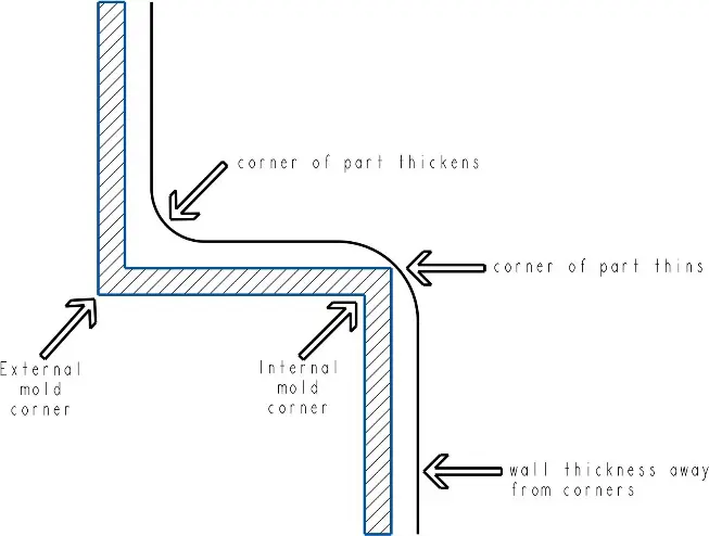
For most engineering thermoplastics, the target nominal wall thickness is between 1.2 mm and 3.5 mm. This range must be adjusted depending on the flow path and glass fiber content. However it is crucial to control the variations in wall thickness. Adjacent wall areas should not differ by more than 25%.
Transitions cannot always be avoided, for example when a dome connects to a thin wall. In such cases, the transition should extend over a length at least three times the wall height.
Isolated thick sections cool down 40 to 50% slower than the surrounding material. This difference in cooling rate is precisely what causes most problems with sink marks and warping.
● Draft Angles for Clean Demolding
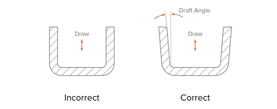
For smooth & non-critical surfaces you should provide a draft angle of at least 1° per side. For textured surfaces, add approximately 1° for every 0.025 mm of texture depth. Heavily textured surfaces may require 5° or more.
Insufficient draft can increase ejection force and cause drag marks, surface damage, part sticking, or deformation. Side actions are normally required only when the geometry creates an undercut relative to the mold-opening direction. Both are more expensive than incorporating the draft angle directly into the design.
● Ribs, Gussets and Bosses
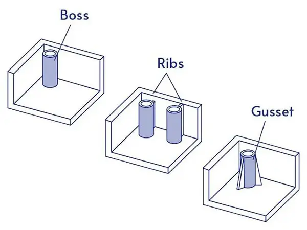
Rib thickness at the base should generally be approximately 40% to 60% of the adjacent nominal wall thickness. Their height should not exceed three times the wall thickness. A radius of 0.25 to 0.5 times the wall thickness at the rib base is recommended to reduce stress concentrations.
The same basic rules apply to bosses. Make them hollow instead of leaving solid cylindrical sections. If a boss bears the load of a fastener it should also have a gusset. Don’t rely solely on wall thickness to withstand shear forces.
Gate Position, Undercuts and Parting Lines
Even a well-designed component can fail if the mold cannot form it cleanly or fill it completely. Component geometry alone is not enough. Decisions at the mold level must also be considered.
Choose Gate Location for Better Flow and Fewer Weld Lines
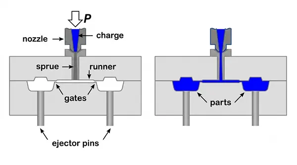
Position the gate at the thickest cross-section so that the holding pressure reaches shrinkage-prone areas before the gate freezes. Position the gate so that the flow length remains as short as possible. This limits shear heating and keeps pressure loss manageable.
Welding lines form wherever two flow fronts meet. Depending on the melt temperature at this point of contact, the tensile strength can decrease by 10 to 30% due to weld lines. Therefore, position the gate so that weld lines are not located on visible surfaces or in load-bearing areas.
Mastering Undercuts Without Significantly Increasing Tooling Budgets
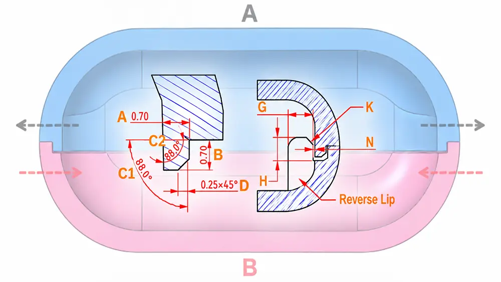
Some geometries cannot be demolded in the main opening direction of the mold, for example side holes, snap hooks or internal threads. Slides or collapsible cores are required for these. This increases tooling costs by $600 to $3500 and extends the lead time by one to two weeks.
Before implementing a slide, consider whether the undercut can be avoided through a design change. A typical solution is to convert a side snap connection into a flexible spring tongue that can yield in the mold’s opening direction.
Common Injection Molding Defects and Their DFM Causes
Every recurring defect traces back to a specific design choice, not chance. This section shows which decision causes which failure, and how to prevent it.
● Sinkholes
Sinkholes appear as shallow depressions on the surface opposite of a boss, rib or thick wall area. They form because these zones cool more slowly than the surrounding wall and the surface shrinks inwards as the material contracts. Therefore, keep the ratio of rib to wall thickness between 40 and 60%.
● Warping
Warping occurs when uneven cooling affects a larger, flatter component rather than just a single feature. Asymmetrical ribs, uneven wall thicknesses and an off center gate position lead to uneven shrinkage across the entire component. Glass fiber reinforced plastics worsen this because the fiber orientation along the flow path increases shrinkage in one direction.
● Short Filling
Short filling occurs when the cavity is only partially filled. The cause is usually an unfavorable gate position. If the gate is too far from thin-walled, slender geometries, the pressure drops there before the plastic solidifies. The same happens if the wall thickness is below the minimum practically processable thickness of the material.
● Flash Formation
Flash is excess plastic that emerges at the parting line or in the area of slides and ejectors. Common causes include worn sealing surfaces or insufficient closing force. Sharp transitions at the parting line provide a more reliable seal than rounded ones. Therefore, the choice of geometry is just as important as the available closing force.
Related Blog Post: Common Injection Molding Defects and Solutions.
What a Good DFM Report Should Contain and How to Obtain One
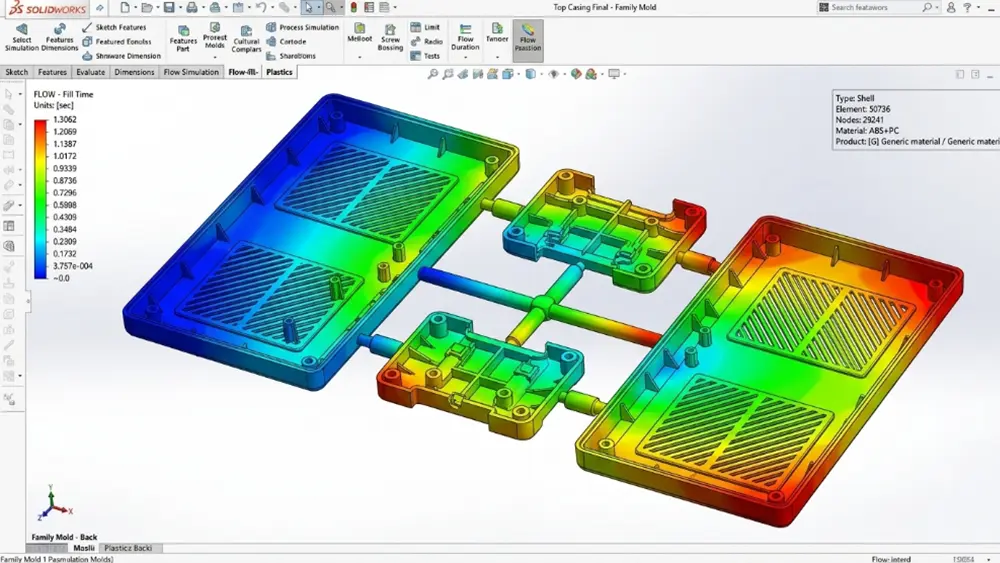
A complete DFM report documents the wall thickness analysis and draft angle verification for each individual surface. It also includes suggestions for gate positions & parting lines and identifies undercuts along with potential tooling solutions. For critical applications it also incorporates the results of a flow simulation. From this, the expected mold filling pattern, weld line formation and warpage risk can be determined.
| Report Element | What It Covers | Defect/Risk It Flags |
| Wall thickness analysis | Nominal wall, variance %, transition zones | Sink marks, warpage |
| Draft angle review | Per-face draft, texture adjustments | Ejection drag, part sticking |
| Gate & parting-line proposal | Gate location, flow length, parting-line path | Weld lines, flash |
| Undercut assessment | Side actions, lifters, or design workarounds | Tooling cost overruns |
| Mold flow simulation | Predicted fill pattern, weld lines, warpage | Short shots, warpage (critical parts only) |
How long should you expect to take for a DFM review?
For simple components, feedback is usually available within 24 to 48 hours. Components with multiple undercuts or thin-walled areas can take up to a week. You should not hurry the DFM review phase, because time pressure is precisely how the defects described above make it into steel.
Conclusion
DFM is most beneficial when applied early in the design process and not discovered after tooling is already complete. Therefore, treat wall thicknesses, draft angles, gating concepts, and undercuts as fixed constraints from the very first CAD iteration.
The RJC Mold engineering team handles DFM analysis and tooling in-house. Send us your CAD file, and we will provide you with a comprehensive DFM report before your design enters the tooling phase.
Related Questions
How many cavities should a production mold have?
The number of cavities depends on your annual production volume, the tolerance requirements of the component and the available molding budget. Multi-cavity or family molds reduce unit costs but require more precise process control to ensure all cavities are filled evenly.
What is a First-Article Inspection (FAI), and why is it important?
An FAI is a complete inspection of the first parts produced in a new mold, including dimensional accuracy and functionality. Without this you may not notice dimensional deviations until thousands of parts have already been injection molded.
How does material selection influence DFM decisions?
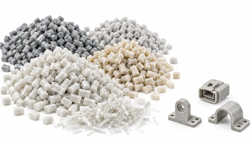
The choice of material determines the shrinkage behavior, the achievable flow length and the cooling behavior. These factors directly impact decisions regarding wall thickness and gate position. Glass fiber reinforced materials shrink differently depending on the direction and require a higher clamping force.
What is a snap-fit connection and what design rules apply to it?
A snap-fit connection is a flexible functional element produced in injection molding, usually a cantilever with a hook, that connects two parts without additional fasteners.
Keep the maximum strain during deflection below the allowable strain specified for the selected material. The allowable value varies significantly by resin grade, temperature, load duration, fiber content, and whether the snap fit will be assembled once or repeatedly.
How does wall design affect cycle time?
Thicker walls require more cooling time before ejection because the heat has to travel a longer distance to reach the mold surface. Even a reduction in nominal wall thickness of 0.5 mm can noticeably shorten the cycle time.