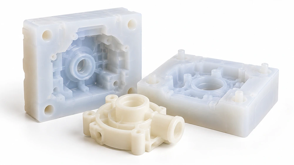
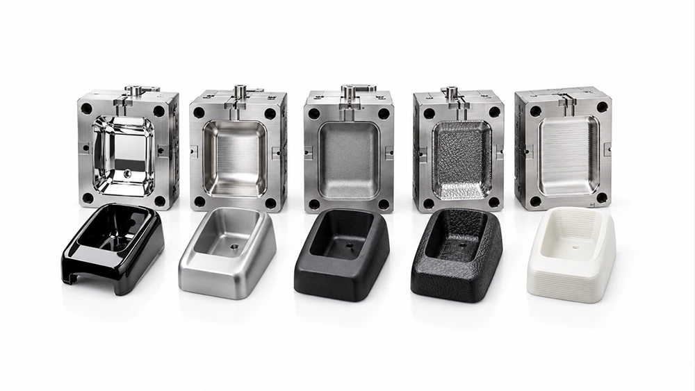
During injection molding, molten plastic pushes the air inside the mold cavity toward unfilled areas. If the air cannot escape in time, it may become compressed and trapped, causing defects such as burn marks, short shots, and reduced weld line strength. Effective venting design requires an understanding of melt flow paths to determine where vents are needed, followed by selecting suitable venting methods and dimensions based on the material and mold structure.
1. How to Determine Venting Locations in Injection Molds
Vent placement directly affects how well a mold cavity fills. When designing the venting system, engineers need to consider the gate location, melt flow direction, and available air escape paths to identify which areas require priority venting.
Identify Venting Areas Based on Melt Flow Direction
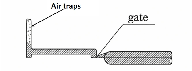
Vent locations largely depend on the melt flow pattern. As the melt advances, it pushes air toward the last-to-fill areas, where air may become trapped as separate flow fronts meet.
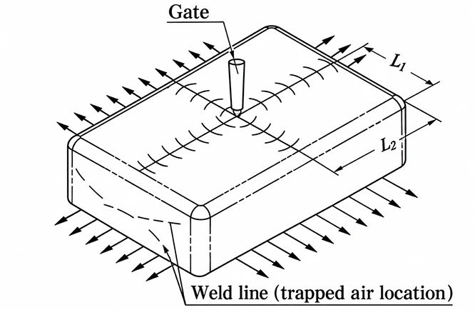
The following illustrations show two rectangular box-shaped parts with different gate arrangements, resulting in different air trap locations.
When the melt enters through a pin gate on the top surface and spreads outward, weld lines and trapped air tend to form near position I when L₂ > L₁.
When the melt enters through a side gate, it advances along flow paths 1, 2, and 3. The flow fronts eventually meet near position II, creating a potential air trap.
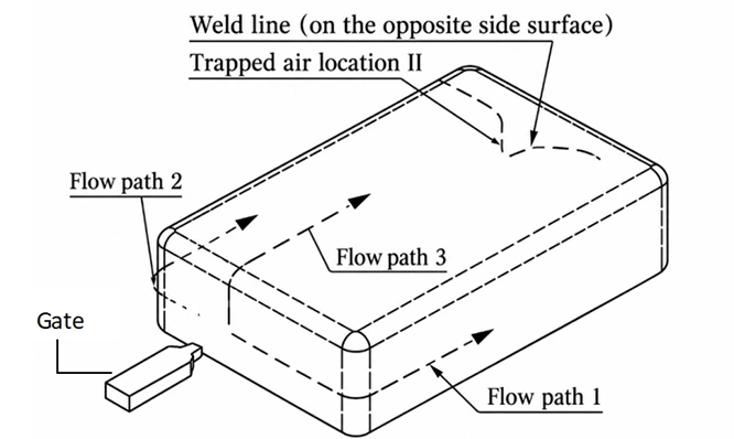
These examples show how gate placement and melt flow paths influence where air becomes trapped. Particular attention should be paid to the last-to-fill areas and locations where flow fronts converge.
How to Identify Primary and Secondary Venting Locations
Venting locations can be classified as primary or secondary based on how easily air becomes trapped and whether alternative escape paths remain available. This helps establish venting priorities.
Primary venting locations include:
- Last-to-fill areas where air is likely to become trapped.
- Locations where converging melt flow fronts enclose pockets of air.
- Areas where trapped air has no other effective escape route.
Secondary venting locations include:
- Areas that require venting during filling but still have other effective air escape paths.
- Locations where additional vents help reduce air resistance and improve filling consistency.
* The distance from the gate alone does not determine venting priority. An area far from the gate may be less critical if air can escape through another path. Conversely, a location closer to the gate may develop an air trap early when separate flow fronts converge.
Case Study: Identifying Primary and Secondary Venting Locations
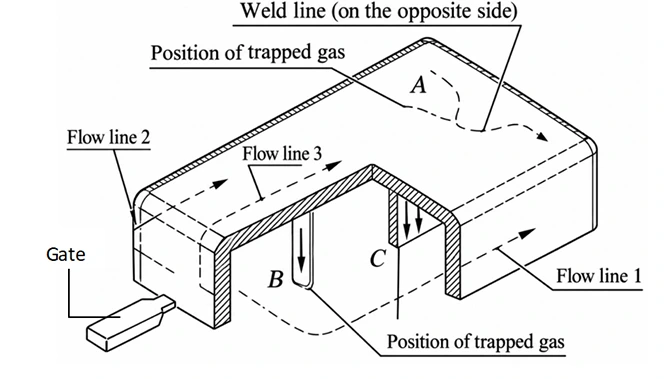
As shown in the illustration, molten plastic enters the cavity through a conventional edge gate and flows along three paths labeled 1, 2, and 3. Weld lines and trapped air form at locations A, B, and C.
Locations B and C are considered primary venting locations. Both are situated within deep internal features. As the melt fills these areas, trapped air has no other effective escape route, making dedicated venting a priority.
Location A can be treated as a secondary venting location. Although air may also become trapped there, venting conditions are relatively more favorable than at B and C. Parting-line vents or other conventional venting methods can provide additional air release.
Which Part Features Are Prone to Localized Air Traps?
The following features deserve particular attention during part and mold design:
Deep ribs and grooves: Air can remain trapped at the ends of narrow or deep cavities as the melt advances.
Blind holes and enclosed recesses: Air inside these features may have no direct escape path to the parting line.
Boss bases: Melt flow around a boss can converge and trap air near its base.
Flow-front convergence areas: When separate melt fronts meet, pockets of air may become enclosed.
Complex core features: Cores can redirect melt flow, creating potential air traps behind or around them.
2. What Are the Common Venting Methods for Injection Molds?
Once venting locations have been identified, the appropriate method should be selected based on the mold structure and the areas where air is likely to become trapped.
Parting Line Venting
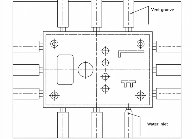
Parting line venting is the most common method. Vent grooves are machined into the parting surfaces of the mold halves, allowing air to escape from the cavity. This method provides good venting capacity and is relatively easy to machine.
Vents are typically placed opposite the gate and along the adjacent sides. For larger or thicker-walled parts, additional vents may also be needed on the gate side.
Ejector Pin Venting
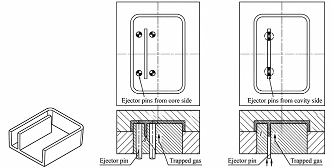
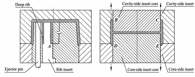
Ejector pin venting uses controlled clearances between ejector pins and their bores to release trapped air. It is useful for deep ribs, bosses, and localized areas that cannot be vented directly through the parting line. Flats or vent grooves can also be machined into the pins to improve airflow.
Insert Venting
Insert venting creates air escape paths through the mating surfaces between mold inserts and the surrounding mold components. It is particularly useful for deep cavities, complex core features, and localized air traps.
Other Venting Methods
Special mold designs may also use venting through slider interfaces, porous metal, or vacuum-assisted systems. Vacuum venting is particularly useful for enclosed cavities and blind features where conventional venting channels cannot provide sufficient air removal.
3. How to Design Injection Mold Vent Dimensions
Basic Vent Structure and Dimensions
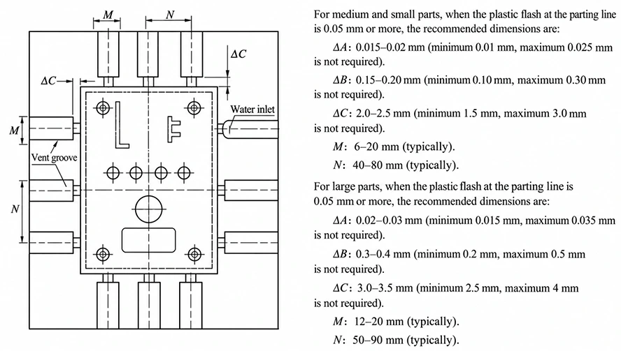
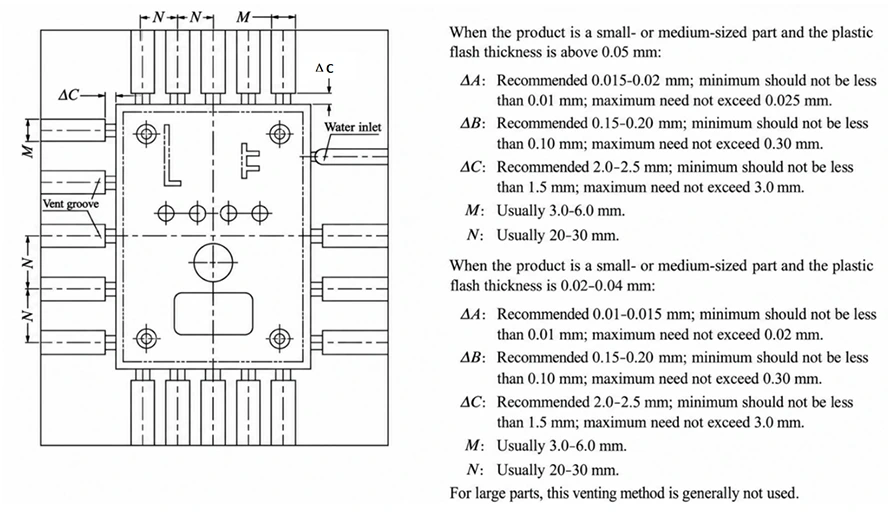
Parting line vents generally consist of a shallow vent land near the cavity and a deeper relief channel behind it. Four main dimensions are involved:
| Parameter | Design Reference |
| Vent Depth | Determined by material properties; refer to the material-specific depth table below. |
| Vent Width | 3–6 mm |
| Vent Land Length | 0.8–2.5 mm |
| Relief Channel Depth | Approximately 0.3–0.8 mm, with further deepening where necessary |
Recommended Vent Depths for Different Plastics
| Plastic Material | Reference Vent Depth (mm) |
| ABS | 0.025–0.051 |
| PC | 0.025–0.051 |
| PA | 0.012–0.020 |
| POM | 0.012–0.030 |
| PP | 0.025–0.051 |
| PEEK | 0.008–0.015 |
| PPS | 0.0076–0.0127 |
Note: These values are initial design references, not universal standards. Different resin grades, fillers, and processing conditions may require different vent depths. Always prioritize the material supplier’s recommendations and verify the final dimensions through mold trials.
Vent Width, Quantity, and Spacing
The layout of vent grooves should be based on part size, melt flow paths, and actual venting requirements. Two common arrangements are:
Fewer, Wider Vents: A smaller number of wider vent grooves, suitable for areas with concentrated venting requirements and sufficient machining space.
More, Narrower Vents: A larger number of narrow grooves distributed around the cavity, suitable when venting is required at multiple locations.
4. Common Venting Problems and Solutions
| Common Problem | Possible Cause | Recommended Action |
| Burn Marks | Localized air traps and compressed air heating | Improve vent placement and airflow paths |
| Short Shots | Air cannot escape quickly enough | Check end-of-fill venting and filling conditions |
| Reduced Weld Line Strength | Converging flow fronts and insufficient local venting | Optimize gate location, flow paths, and venting |
| Flash | Excessive vent depth or poor mold fit | Check vent dimensions and parting surfaces |
| Clogged Vents | Carbon buildup, deposits, or contamination | Clean vents and review material and process conditions |
Venting is not the only factor behind injection molding defects. Troubleshooting should also account for injection speed, melt temperature, mold temperature, material drying conditions, and mold fit.
FAQs
Q1: Is it better to have more vents in an injection mold?
Not necessarily. Additional vent locations or greater effective vent area can improve air evacuation, but material characteristics still matter. Some materials containing special flame retardants or additives may be sensitive to excessive venting. Follow the recommendations for the specific resin grade.
Q2: When venting is insufficient, should the vents or gate location be modified first?
Start by examining the air trap locations and melt flow paths. If the gate arrangement is appropriate but the venting capacity is inadequate, improve the vents first. If the gate causes unfavorable flow-front convergence, consider changing the gate location or flow path.
Q3: What should be considered when venting high-temperature plastics?
Materials such as PEEK and PPS require venting guidelines specific to the resin grade. High mold temperatures, fillers, and mold wear resistance should also be considered.
Q4: Why can venting problems appear during mass production even when mold trials were successful?
Long production runs can lead to carbon buildup, blocked vents, or changes in mold fit. Regularly inspect and clean venting channels while monitoring material conditions and processing parameters.
Q5: Where do the gases that need to be vented during injection molding come from?
They mainly come from air originally present in the cavity, water vapor released from moisture in the plastic, gases generated by thermal degradation of the polymer, and volatile compounds released from certain additives.