The sprue is the entry point of an injection mold’s runner system. It directs molten plastic from the injection machine nozzle into the mold and connects to the downstream runners. Its structure, dimensions, and location affect melt flow, pressure loss, and demolding performance. This article introduces sprue structure and key design considerations, along with runner design and flow balancing in multi-cavity molds.
1. What Is a Mold Sprue?
A sprue is the main channel connecting the injection machine nozzle to the mold runners. It is the first section of the flow channel that molten plastic passes through after entering the mold. The sprue is typically formed by a sprue bushing installed on the fixed side of the mold, which guides molten plastic into the mold.
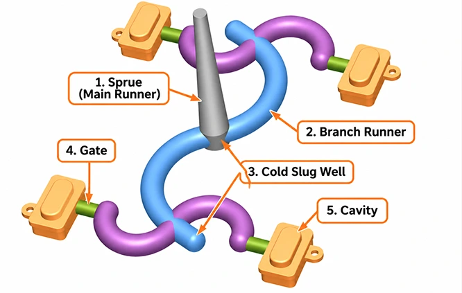
In conventional cold runner injection molds, the feed system consists of four main components:
Sprue: Connects the injection machine nozzle to the internal runner system and delivers molten plastic.
Runner: Distributes molten plastic from the sprue to one or more cavities.
Gate: Connects the runner to the cavity and controls the entry location and flow rate of the melt.
Cold Slug Well: Collects cooler material at the melt front, reducing the risk of cold material entering the cavity.
The typical flow path is: Injection Machine Nozzle → Sprue → Runner → Gate → Cavity.
2. Sprue Structure and Design
Sprue design involves nozzle connection, channel dimensions, melt flow, and demolding requirements.
Sprue Bushing
The sprue bushing is installed on the fixed side of the injection mold. It contains a tapered channel that guides molten plastic from the injection machine nozzle into the mold.
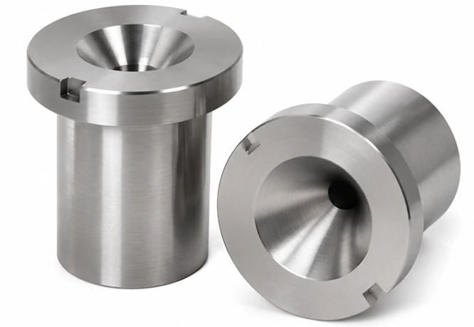
The sprue bushing is typically designed as a separate insert, located and secured within the mold plate for easy machining, removal, and replacement. As it is repeatedly exposed to high-temperature melt erosion and contact pressure from the injection machine nozzle, it is usually made of mold steel with sufficient hardness, wear resistance, and heat resistance.
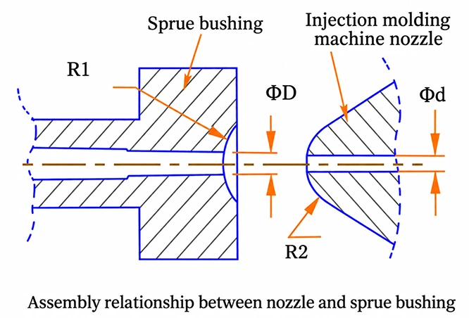
Sprue and Injection Machine Nozzle Fit
Inlet diameter relationship: D = d + (0.5–1) mm
Spherical radius relationship: R1 = R2 + (1–2) mm
Sprue Location and Taper Design
- The sprue is typically aligned with the center of the mold.
- Special cavity layouts require an off-center sprue design and corresponding adjustments to the ejection mechanism.
- The sprue has a tapered shape with a smaller inlet and a larger outlet.
- The taper angle is typically 2°–4°and can be adjusted according to the diameter at the larger end of the sprue.
- The inner surface of the sprue channel should be well polished to facilitate demolding.
3. Runner Structure and Sizing
Runners connect the sprue to the gates, delivering and distributing molten plastic to individual cavities. Their cross-sectional shapes and dimensions affect melt flow resistance, heat loss, and filling efficiency.
Common Runner Cross-Sectional Shapes
Common runner cross-sectional shapes include circular, regular hexagonal, U-shaped, square, trapezoidal, semicircular, and rectangular profiles. These shapes differ in flow resistance, heat loss, and machining difficulty, as shown in the figure below.
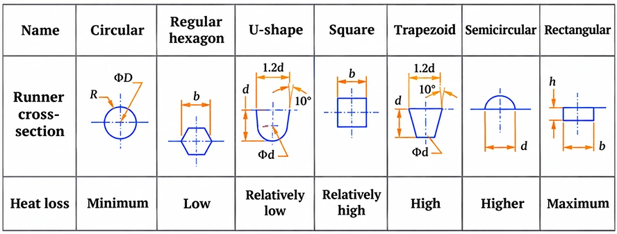
Circular runners offer high flow efficiency, while U-shaped and trapezoidal runners provide advantages in machining and demolding.
Runner Sizing
Runner dimensions are determined by runner length, plastic flow characteristics, and part wall thickness. Key design considerations include:
Runner Length and Diameter: Longer runners generally create greater resistance to melt flow, requiring a larger cross-section.
Runner Size: Runners should be kept as short as possible and appropriately sized to minimize material consumption while meeting filling and packing requirements. Undersized runners can cause excessive pressure loss and premature solidification.
Cross-Sectional Changes: Abrupt changes in cross-sectional area at runner junctions should be avoided to reduce local flow resistance.
Runner and Gate: The minimum cross-sectional area of the runner should be greater than that of the gate to ensure smooth melt flow and meet packing requirements.
Different plastics have different flow characteristics, and runner dimensions need to be adjusted accordingly.
| Plastic Material | Flow Characteristics | Runner Size Reference |
| PE, PA, PP | Good flowability | Short runners can use a diameter of approximately 2.5 mm |
| HPVC, PC, PMMA | Relatively poor flowability | Larger diameters can be used for longer runners |
For typical plastic parts with wall thicknesses of 1.0–2.0 mm, a circular runner diameter of 3.0–4.0 mm can serve as a design reference. The final dimensions should be determined according to the material grade, runner length, and part geometry.
Based on our years of injection molding experience, changes in runner diameter have a more noticeable effect on melt flow when the diameter is below 5–6 mm. Beyond 8 mm, further increases in diameter generally provide limited improvements in flow.
4. Runner Balance Design in Multi-Cavity Molds
Multi-cavity molds require a well-designed runner layout to distribute molten plastic evenly across all cavities. Common runner configurations include radial, tree-shaped, and multi-level branching layouts. The specific configuration depends on the number and arrangement of cavities, as shown below.
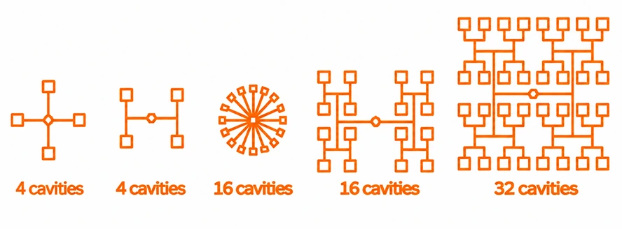
The runner system should maintain similar flow lengths, cross-sectional areas, and pressure drops from the sprue to each cavity gate, allowing the cavities to fill at approximately the same time and pressure.
5. Common Sprue and Runner Design Problems and Solutions
| Common Problem | Main Cause | Solution |
| Sprue sticking | Insufficient taper, rough surface | Increase taper, improve polishing |
| Excessive pressure loss | Long or undersized runners | Optimize runner length and size |
| Premature runner freeze-off | Undersized runners, rapid cooling | Adjust runner dimensions and temperature |
| Uneven cavity filling | Unbalanced runner system | Optimize runner layout and gate size |
| Excessive material waste | Oversized runners | Reduce runner volume, optimize layout |
These problems need to be evaluated based on actual molding conditions. Some can be resolved through mold design modifications, while others require adjustments to melt temperature, mold temperature, injection speed, and holding pressure parameters.
Conclusion
The sprue is a key entry point in the injection mold’s runner system, and its design directly affects melt delivery and subsequent cavity filling. Proper selection of the sprue bushing, nozzle fitting dimensions, sprue taper, and runner cross-section, combined with balanced runner design in multi-cavity molds, helps reduce pressure loss, improve filling performance, and minimize material waste.