Plastic Injection molds are the core tools in injection molding process, with their quality directly impacting product precision, appearance, and production efficiency. From product conception to final finished goods, molds serve as the pivotal link throughout the entire production process. Whether for consumer electronics enclosures, medical device components, or automotive parts, high-quality injection molds ensure production stability, reduce defect rates, and extend equipment lifespan. Therefore, a deep understanding of injection mold design, structure, manufacturing, and maintenance management is crucial for plastic product manufacturers. This complete guide is intended to serve as a reference and provide helpful guidance.
I. Mold Design Phase
The following design considerations should guide the tooling design process to ensure manufacturability, reliability, and efficiency.
Stage 1: Pre-Mold Preparation and Review
Core Principle: Analyze first, communicate next, then design. Never rush into mold parting line design upon receiving product drawings.
1. Product Design Drawing Preprocessing and Analysis
Inspection and Modification: Examine product structure, perform necessary tolerance adjustments, draft angle treatment, and step height modifications.
Preliminary Conceptualization: Based on preprocessing results, tentatively determine parting lines, product structure, and gate locations.
2. Thoroughly Understand Customer and Production Requirements
Injection Molding Machine Specifications: Confirm the customer’s injection molding machine tonnage and model. This determines critical mold components—gate sleeves, locating rings, ejector pins, mold base dimensions, and overall mold height—and is essential for ensuring the mold can be mounted and operated on the machine.
Product and Material Details:
Material Confirmation: Specify the exact grade of the final production material and whether it is modified. Obtain accurate shrinkage rates; do not rely on assumptions based on experience.
Issue Analysis: Analyze potential problems like parting lines.
Assembly & Function Understanding: Understand the product’s end use and assembly relationships to distinguish visible/non-visible surfaces. Identify structures (e.g., draft angles, undercuts) that can be optimized or simplified.
Optimization Mindset: Mold designers bear the responsibility to simplify complex issues and proactively offer professional suggestions to product engineers for optimizing unreasonable structures.
Special Requirements: Confirm in advance whether the mold requires date stamps, engraved inserts, vent inserts/pins, etc., to reserve space during initial design.
Stage 2: Mold Structure Design
Core Principles: Strive for simple, reliable structures that facilitate machining and assembly while meeting functional requirements.
1. Parting Line and Parting Surface Design
Parting surface design should follow the product’s natural contour and be kept as simple as possible.
Prioritize manufacturability: if the functional requirements permit, design the part so it can be released by a straight pull rather than relying on side-core mechanisms. For non-precision molds, small lifters or thin penetrating inserts should be reduced or eliminated.
Reliability: ensure larger engagement angles, maximize the contact area, and keep the support land as wide as possible, while fully considering the ease of mold closing.
2. Forming Mechanism Design (Sliders & Angled lifter)
Core Principle:Fully utilize trigonometric relationships to realize undercut release through controlled angled motion.
Slider (β): The slider angle β is determined by the angle of the angle pin and must be larger than it. If β is equal to or smaller than the angle pin angle, the locking surface cannot effectively lock the slider, or the angle pin will bear excessive lateral force, leading to bending or damage.
Angle pin (α): The angle pin angle α should be kept small (typically 15°–25°), and a sufficiently large diameter should be selected to ensure adequate strength.
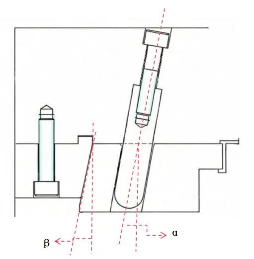
β=α+2°~3°(Prevent interference during mold closing and reduce friction in the mold)
α≤25
Verification: After designing any special structure, feasibility must be validated through simulated mold opening and closing operations.
3. Mold Base Selection and Insert Assembly Design
Select based on requirements: Choose two-plate molds, and three-plate molds, or hot runners according to product characteristics.
Assembly principles: Prioritize simplified machining, material savings, favorable molding (venting), and ease of replacement of wear-prone components. Weak or vulnerable areas should be assembled with separate inserts.
4. Standard Component Layout
Conflict Resolution: This represents the primary design challenge—the ejection system and cooling channels often interfere with each other, requiring iterative adjustments to achieve balance.
Ejection Design: Prioritize placement in areas with high clamping force and structural integrity (e.g., ribs, pillars, edges) to prevent flash or deformation. Select ejector pins, ejector blocks, or ejector plates based on the structure.
Cooling Design: Water channels should prioritize areas with high clamping force (i.e., heat concentration).
Sequence: Typically, initially arrange ejector pins, then design water channels, coordinate both, and finally add other standard components (e.g., screws), adhering to balanced symmetry principles.
Stage 3: Design Verification
1. Mandatory Checks
Draft Analysis: Verify no undercuts exist on all inserts.
Interference Check: Conduct comprehensive interference checks using 3D software—this is paramount.
Mold Opening/Closing Simulation: Simulate any uncertain motions.
Machinability and Assembly Review: Ensure all parts are machinable and the entire mold assembles smoothly.
2. Final Philosophy: Finding the Balance Point
Mold design is the process of finding the optimal balance between cost, precision, strength, lifespan, and production efficiency. There is no such thing as a perfect design; only the most suitable, reasonable design for the current product, budget, and production conditions. Mastering core principles and processes, then applying them flexibly to specific problems, is the key to designing robust and efficient molds.
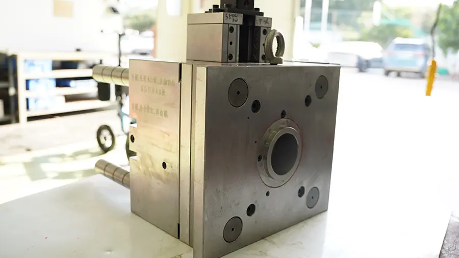
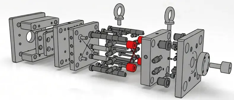
II. Mold Structure
The structure of an injection mold is the physical implementation of the mold design. Each component has a specific function to ensure stable operation of the mold on the injection molding machine.
There are many types of mold, including single-cavity molds, multi-cavity molds and two-color molds, , each designed for specific production requirements. The following sections focus on the structure of a standard injection mold, which serves as a representative example for most conventional plastic molding applications.
1. Cavity Plates and Core Plates
Cavity plates and core plates are the direct molding components for plastic parts, forming the mold cavities. Cavity plates form the product’s external shape, while core plates create internal cavities. The hardness, wear resistance, and thermal conductivity of these plates directly impact product dimensional accuracy and surface quality. Typically, cavity and core surfaces require precision grinding and polishing to ensure surface finish and durability.
2. Gate System
The runner system comprises the main runner, sub-runner, and gates, responsible for uniformly distributing molten plastic into each cavity. Multi-cavity molds require flow balance calculations to ensure even filling across all cavities and prevent excessive product variation. Hot runner systems reduce scrap and enhance production efficiency, particularly for high-volume molds.
3. Cooling System
The cooling system regulates mold temperature via water or oil channels, accelerating plastic solidification. A well-designed cooling system minimizes warpage, sink marks, and surface defects. Its layout must ensure uniform temperature distribution across all cavity areas while facilitating maintenance and cleaning.
4. Ejection System
The ejection system includes ejector pins, ejector plates, and slides to expel molded parts from the mold. Ejection force must be evenly distributed to prevent part deformation or surface damage. For complex-shaped components, slide ejection or side ejection are common solutions.
5. Guide System
The guide system, composed of guide pins and bushings, ensures precise alignment between the moving and fixed mold halves during closure. Its accuracy directly impacts injection precision and product surface quality. Regular wear inspections and lubrication maintenance are essential for long-term operation.
6. Clamping System
The clamping mechanism maintains stable pressure during mold closure, ensuring complete filling of the cavity with molten plastic. Insufficient clamping force causes melt leakage, compromising product dimensions and surface quality.
7. Auxiliary Components
Auxiliary components—including springs, screws, stop plates, and support plates—adjust mold structure and ensure operational stability. During prolonged production, the quality and layout of these components directly impact mold longevity and maintenance costs.
III. Mold Fabrication
Mold manufacturing brings design concepts to life, involving material selection, machining processes, and assembly debugging.
1. Material Selection
Common mold materials include P20, 718, and H13 steel. Material selection requires consideration of hardness, wear resistance, thermal conductivity, and corrosion resistance. High-hardness steels are suitable for high-volume production or molds subject to significant wear, while steels with good thermal conductivity facilitate faster cooling and enhance production efficiency.
2. Machining Processes
Mold fabrication primarily employs CNC machining, EDM (Electrical Discharge Machining), grinding, and polishing. CNC machining handles roughing and finishing operations to ensure dimensional accuracy and surface geometry. EDM is ideal for intricate cavities and fine structures. Cavities and cores undergo grinding and mirror polishing to achieve a smooth product surface. Strict control of machining parameters is essential to prevent material stress deformation.
3. Assembly and Debugging
After machining, mold components undergo precision assembly with inspections of the guide system, ejection system, and clamping accuracy. Post-assembly requires trial molding to verify injection balance, cooling efficiency, and smooth ejection operation. Trial molding records injection parameters and product dimensions for mass production reference.
4. Trial Runs and Optimization
Design or manufacturing deficiencies may surface during trial runs, such as short shots, flash, warping, or ejection difficulties. Mold performance can be optimized by adjusting gate locations, cooling systems, or ejection mechanisms. Trial run data also supports subsequent mold maintenance and lifespan assessment.
IV. Mold Maintenance and Management
Mold maintenance is crucial for ensuring long-term stable production and extending mold lifespan, encompassing daily upkeep, periodic inspections, and lifespan management.
1. Daily Maintenance
After each production run, clean residual plastic, oil stains, and contaminants from the cavities. Regularly apply rust-preventive oil or lubricants to sliding surfaces and ejection systems to prevent wear and jamming. Daily checks should also verify that fasteners and auxiliary components remain secure.
2. Periodic Inspection
Regularly examine mold closing accuracy, guide systems, ejection mechanisms, and cooling circuits. Replace or repair severely worn or damaged components promptly. Scheduled maintenance prevents unexpected production issues and maintains consistent product quality.
3. Mold Lifecycle Management
Evaluate mold lifespan based on usage frequency and production volume. Develop specialized maintenance plans for high-precision or high-output molds. Lifecycle management encompasses wear monitoring, mold refurbishment, and maintenance records to help enterprises rationally schedule production and maintenance plans.
Summary
Injection molds represent a systematic, precise, and interconnected process spanning design, structural determination, manufacturing, injection molding operations, and maintenance management. The design phase determines product feasibility and production efficiency, while mold structure and manufacturing techniques dictate product forming quality. Scientific maintenance management extends mold service life, ensuring long-term stable production. Through in-depth understanding and standardized management of the entire injection mold life cycle, enterprises can achieve high-quality, high-efficiency plastic product manufacturing, providing robust support for production efficiency and market competitiveness.