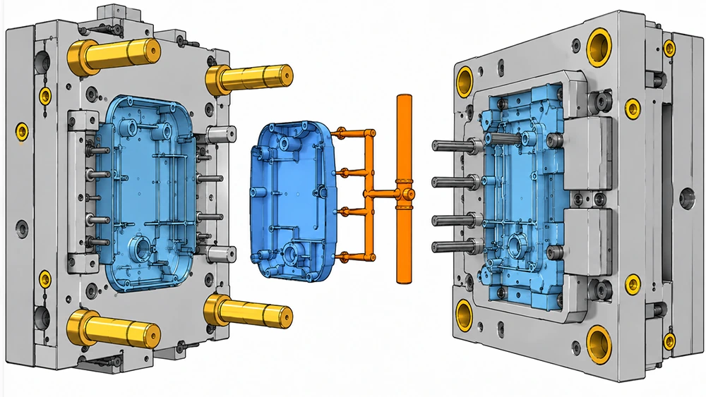
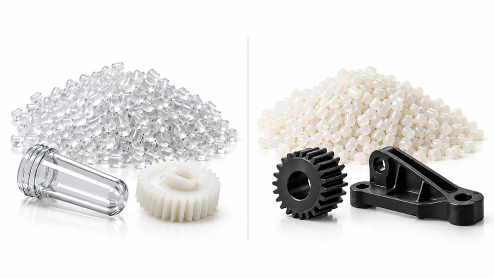
Most process engineers tackle injection molding cycle time from the wrong end. They adjust machine parameters first, while the biggest gains often come from the cooling layout and mold design. If your press is not producing the expected number of shots per hour, here is where to start looking.
What Is Injection Molding Cycle Time?
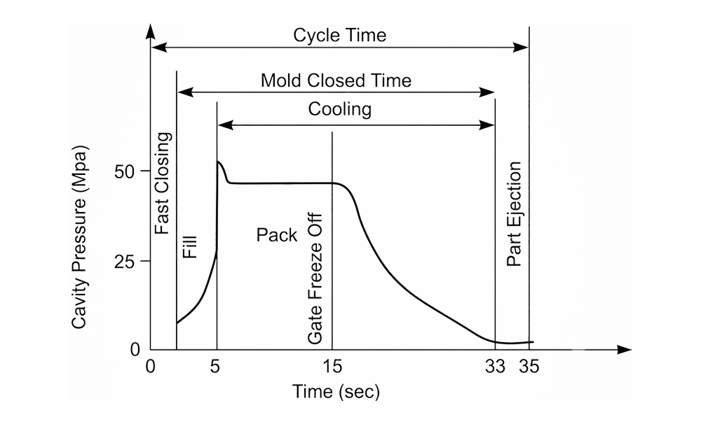
Injection molding cycle time is the time required to complete one shot, from mold close to mold open. It has four phases:
- Filling
- Packing/Holding
- Cooling
- Ejection
Research often shows that the cooling phase takes more than 50% of the total cycle time. If you want to reduce cycle time, work in order of impact instead of adjusting parameters at random.
Why Reducing One Phase Is Not Enough
Cycle time reduction is not about cutting seconds from one stage in isolation. A press may hit a 28-second target and still waste time in filling, packing, cooling, or ejection.
The goal is to remove avoidable time without pushing the problem into another phase. For example, reducing cooling too aggressively may create warpage, sink marks, or unstable dimensions. Effective cycle-time work protects both output and part quality.
Must Read: The Impact of Cooling Time on Quality and Efficiency in Injection Molding.
Break the Cycle into Phases: Where Every Second Actually Goes
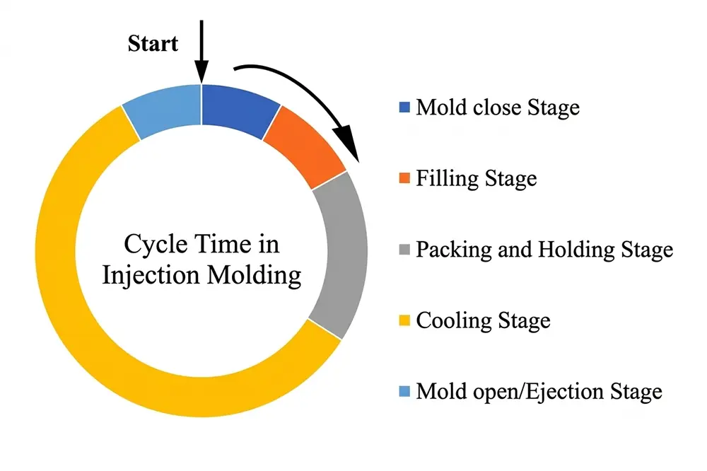
The injection molding cycle can be divided into four separate phases:
T(cycle) = t(fill) + t(pack) + t(cool) + t(eject)
Take a 2.5 mm-wall PP housing and a 30-second cycle as an example. A realistic split would be 2 seconds of filling, 5 seconds of packing/holding, 18 seconds of cooling, and 5 seconds for mold open/ejection. Cooling takes 60% of the press time before any parameter is changed.
The dominant phase varies with part geometry and resin. For example, a thin-wall (<1.5 mm) food container is often limited by injection speed and pressure, while a 4 mm-wall structural bracket is more likely to be limited by cooling. If the dominant phase is misidentified, effort is spent on the wrong variables.
Read Your Cycle Data Before Adjusting Anything
Extract a phase-by-phase breakdown from the press controller before adjusting anything. If cooling takes more than 55% of the total cycle time, the main issue is usually not the machine controller but the mold. The optimizations below are ordered by that diagnostic.
Cooling System Optimization: The Highest-Yield Lever
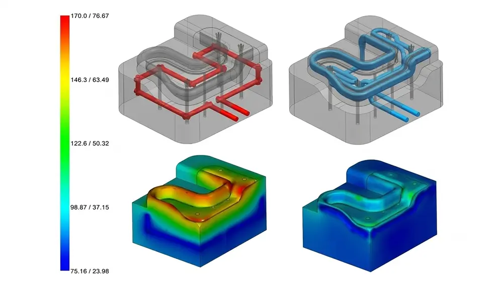
In most thermoplastic parts, the cooling phase accounts for the largest share of total cycle time. That makes it the highest-return target before any machine parameter is changed. Three geometry-related variables control cooling efficiency:
- Channel Distance: Maintain a maximum distance of about 1.5x the channel diameter from the cavity surface. Beyond that, heat-transfer efficiency drops sharply.
- Flow Regime: Turbulent flow (Reynolds number >10,000) can remove heat 3-5 times more effectively than laminar flow. Most engineers monitor the temperature setpoint, but the more important variable is flow rate.
- Temperature Uniformity: Keep the temperature difference between inlet and outlet water at <=5°C. A wider spread usually indicates flow restriction or scale buildup inside the channels.
Conformal Cooling for Geometrically Constrained Tools
Straight-drilled channels follow direct paths, which often leaves corners, deep cores, and ribbed areas under-cooled. Conformal cooling channels made with DMLS additive manufacturing run along the cavity contour at a consistent distance. On complex shapes, they can reduce cooling time by 20-40%.
Expert’s Advice: Conformal cooling molds are expensive to build. They make sense mainly for tools that will run at high volume over a long period.
Related Blogpost: Design and optimization of mold cooling systems in injection molding
High-Conductivity Inserts for Targeted Hot Spots
Deep cores and thick bosses require more focused heat extraction. Beryllium copper (BeCu) or CuCo alloy inserts can do this without a complete tool rebuild. They are less costly than full conformal tooling and can deliver results faster.
Mold Design and Gate/Runner Optimization: Fill Time and Open-Eject Time
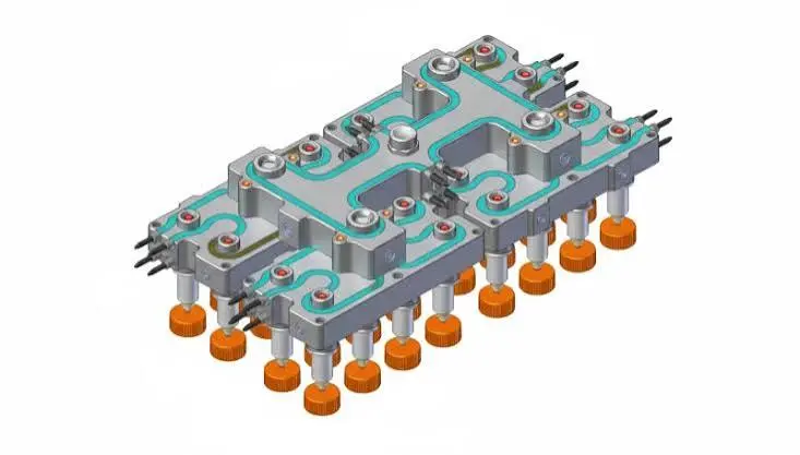
While the cooling phase takes most of the cycle time, the remaining time is controlled by mold geometry: how quickly the cavity fills, how efficiently material is packed, and how fast the mold opens and ejects the part.
Hot Runner Systems and Runner Volume
In a cold-runner mold with a thick sprue, the runner—not the part—can become the cycle-controlling section. In high-cavitation family molds, runner volume can account for 30-40% of the total shot weight.
A hot runner system eliminates runner cooling time. It also reduces regrind and improves shot-to-shot consistency.
Related: Hot Runner vs Cold Runner Mold: Cost, Pros and Cons
Gate Location, Runner Balance and Ejection Speed
Injection pressure and hold time depend on gate position. Placing the gate in the thickest section reduces injection pressure and hold time. Conversely, a gate placed on a thin wall requires higher injection speed and lengthens the packing phase.
In a multi-cavity tool with multiple runners, hold time is set by the slowest cavity. All other cavities pay that penalty on every shot. These losses can be reduced by designing geometrically or rheologically balanced runners.
Ejection and mold open/close speeds are often left at conservative startup defaults, trapping 1 to 3 recoverable seconds per cycle.
Scientific Molding and Machine Parameter Optimization
In scientific molding (or decoupled molding), the fill and pack phases are separated. The fill phase is velocity-controlled to about 95%-98% volumetric fill. The pack/hold phase is pressure-regulated. This separation is the basis for reducing machine-level cycle time. Without it, finding the true gate-freeze time becomes guesswork.
Eliminating Over-Specified Hold Time
After switchover, cavity pressure drops as the gate freezes. When the pressure stabilizes, the gate is closed. Any hold time after that point adds no material; it only increases cycle time. In tools set up empirically and never revisited, 3 to 5 seconds of excessive hold time is common. Cavity-pressure decay analysis can remove that extra time.
Parallel Screw Recovery: The Zero-Cost Fix
Screw recovery should finish within the cooling window. If it does, it does not add cycle time. If it extends beyond cooling, it becomes the cycle-limiting step. Adjusting screw speed and back pressure to keep recovery within the cooling window requires a timer comparison, not a tool change.
Material Selection and Part Design: The Upstream Decisions
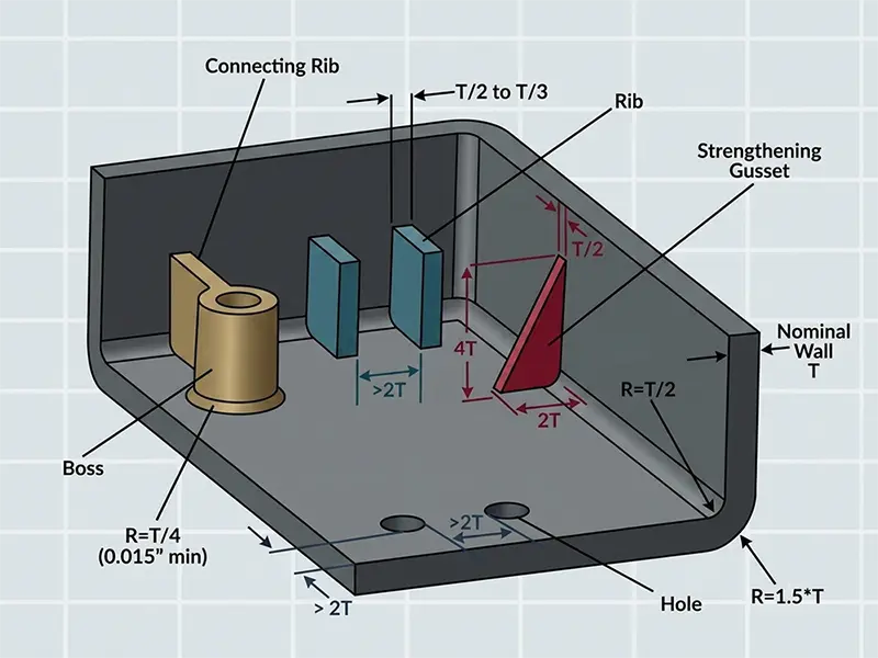
The upper limit for all downstream optimization is set by part geometry and resin family. No process improvement or cooling-system redesign can fully compensate for the cost of a poorly designed part.
Wall Thickness: The Highest-Leverage DFM Decision
Cooling time is proportional to the square of wall thickness. Doubling wall thickness quadruples cooling time. Reducing a structural part from a 4 mm wall to a 3 mm wall can deliver more cycle-time savings than any machine or mold adjustment. At the DFM stage, the change is free; after the tool steel is machined, it can cost thousands.
Resin Selection as a Cycle Time Input
High-flow grades of the same base resin, such as high-MFI polypropylene, reduce injection pressure and fill time. At the same wall thickness, semi-crystalline resins (PP, PA, POM) solidify faster than amorphous resins (ABS, PC). This means resin family is a cycle-time input during design.
When hygroscopic resins such as PA and PC contain high regrind percentages, melt-flow consistency can suffer. This forces more conservative process settings and indirectly lengthens the cycle.
To Sum Up
Injection molding cycle time is not a single variable. It is the result of interdependent decisions. Cooling design affects heat transfer, mold geometry directs flow, process parameters influence pressure and temperature, part design establishes wall thickness, and material selection affects solidification speed. If one factor is neglected, the benefit of the others is limited.
For high-volume injection molding projects, cycle time should be considered during DFM and mold design, not after the tool is already running. RJC Mold helps customers review part geometry, cooling layout, runner design, and production requirements before tooling, so the mold is built for both quality and efficiency from the start.
Related Questions
● How long does it take to reduce injection molding cycle time?
The result depends on where the losses are. A process fix, such as removing over-specified hold time, can show results in one shift. A mold redesign or conformal cooling upgrade requires tooling lead time, but the benefit is longer-lasting.
● Can reducing cycle time affect part quality?
Not if it is done correctly. Scientific molding helps ensure that cycle-time reductions are process-based, not just pressure-based. Quality issues usually occur when engineers reduce time at random, not when they remove real waste.
● At what production volume does cycle time optimization justify the investment?
In high-cavitation or high-volume runs, even a two-second reduction can have a significant impact over millions of shots. For low-volume tools, process-level fixes usually have the fastest payback because the initial cost is low.
● How does conformal cooling differ from straight-drilled cooling channels?
Straight-drilled channels cannot access corners or cover complex geometry such as ribbed sections or deep cores. Conformal channels, in contrast, stay at a consistent distance from the cavity profile. They are fabricated by DMLS and can reduce cooling time by 20-40% on complex geometries.