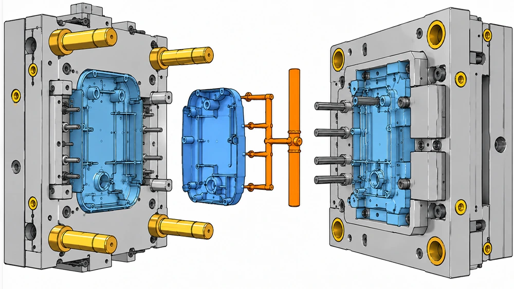
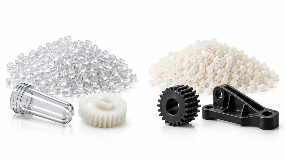
When performing DFM analysis for injection-molded parts, we often find that designers overlook draft angles. It may seem like a minor design detail, but it directly affects part ejection, surface quality, and mold life.
There is no single draft angle that works for every part. Part depth, surface texture, plastic material, and mold structure can all affect the final angle required.
1. What Is a Draft Angle?
A draft angle is a slight taper added to the vertical surfaces of an injection-molded part that run parallel to the direction of mold release. It helps the part release more smoothly from the core or cavity.
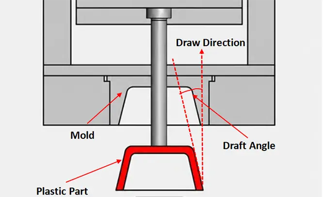
For example, a completely vertical sidewall has a draft angle of 0°. If the wall gradually tapers outward by 1° along the direction of mold release, then that sidewall has a 1° draft angle.
2. Why Are Draft Angles Necessary?
As molten plastic cools, it shrinks and may grip tightly around the mold core, creating frictional resistance during ejection: f= μ × Fn
Where μ is the coefficient of friction between the plastic and the mold surface, which is affected by the material, surface roughness, and surface condition; Fn is the normal force generated by plastic shrinkage.
After a draft angle is added, the frictional resistance in the direction of mold release can be expressed as: f= μ × Fn × cosα

As the draft angle α increases, the resistance to mold release decreases. However, because practical draft angles are usually relatively small, the more important function of draft is to help the part separate from the mold surface more quickly, reducing continuous contact and friction during ejection.
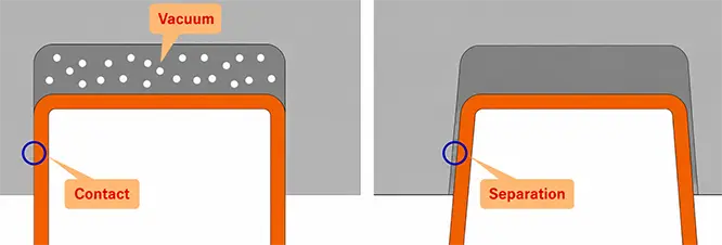
For high-gloss, smooth appearance surfaces that fit closely against the cavity, insufficient mold venting may also create a certain degree of vacuum suction, making it more difficult for the plastic part to fully separate from the cavity half.
3. How Much Draft Does an Injection-Molded Part Need?
For most standard injection-molded parts, 1°–2° is a common starting range.
However, this is only a starting point. It does not mean every part should automatically use a 1° or 2° draft. Deeper sidewalls, textured surfaces, or materials with higher release resistance may require a larger draft angle.
Common Draft Angle Guidelines
| Part Condition | Typical Reference Range |
| Standard smooth sidewalls | 1°–2° |
| Limited design space | Starting at around 0.5° |
| Deep sidewalls or cavities | Usually require additional draft beyond the base angle |
| Lightly textured surfaces | Around 3° |
| Deeply textured surfaces | 5° or more |
| Ribs, bosses, and other vertical features | Usually require at least some draft |
| Shutoff mating surfaces | Usually require a larger angle |
These values are useful as preliminary design references, not fixed standards.
4. What Factors Determine the Required Draft Angle?
1) Part Height and Draft Depth
In general, the greater the height or depth of a part along the mold-release direction, the more significant the release resistance becomes, so a larger draft angle is usually required.
The relationship between draft angle, height, and dimensional offset can be expressed as: tan θ = X / H
where θ is the draft angle, (H) is the draft height, and (X) is the one-sided dimensional offset.
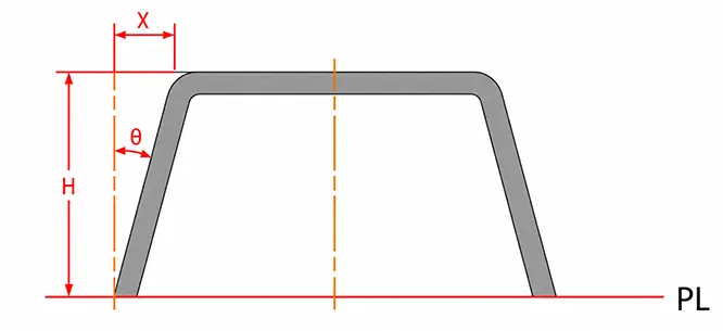
For a fixed height, a larger draft angle produces a greater dimensional offset. Therefore, the design must strike a balance between smooth mold release and dimensional requirements.
2) Surface Texture
Surface condition directly affects release resistance.
High-gloss surfaces: Smooth surfaces can generally use a smaller draft angle. However, scratches and drag marks are highly visible on high-gloss surfaces, so sufficient draft should still be provided in the actual design.
Textured surfaces: Texture increases friction and mechanical engagement during mold release. The deeper the texture, the larger the draft angle required. Light textures can typically be evaluated starting at around 3°, while deeper textures may require 5° or more.
For specified textures such as Mold-Tech, the actual draft angle should be confirmed according to the specific texture number and texture depth.
3) Plastic Material and Shrinkage
Different plastics have different shrinkage rates, hardness levels, and friction characteristics, all of which affect mold release.
Rigid materials have less ability to deform, so insufficient draft can more easily result in drag marks or stress whitening. Softer materials can deform more readily, but some also have relatively high coefficients of friction and may still require larger draft angles.
For transparent materials such as PC and PMMA, special attention must also be paid to drag marks and scratches. As a result, both the draft angle and mold surface quality become more critical.
4) Part Geometry and Mold Design
Draft angles must always be designed according to the actual direction of mold release.
Outer walls, inner walls, ribs, bosses, holes, grooves, shutoff surfaces, and similar features should all be checked in relation to the parting line and the locations of the core and cavity.
Special attention should be paid to ribs and screw bosses:
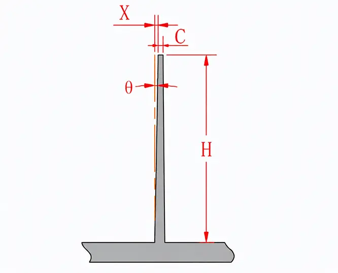
Ribs: As shown below, the larger (X) becomes, the smaller the rib-tip thickness (C) becomes, which makes injection molding more difficult. Therefore, ribs should be kept as short as practical so that a larger draft angle can be used.
Screw bosses: The internal holes of screw bosses often have relatively tight dimensional requirements. To maintain the required hole diameter and tolerance, the draft angle may need to be very small or, in some cases, even 0°. These structures usually require better mold surface polishing and properly positioned ejector features nearby to reduce release resistance.
All surfaces that are essentially parallel to the mold-release direction should be checked to determine whether draft is required.
5. What Happens If the Draft Angle Is Too Small?
Insufficient draft causes more than just a part that is “difficult to remove.”
In actual production, it may lead to:
Difficult mold release: The part grips tightly around the core and requires greater ejection force.
Surface scratches or drag marks: Continuous friction between the part and mold during ejection can leave visible marks on the sidewalls.
Part deformation: Excessive ejection force can cause thin-walled parts or deep housings to bend or deform.
More visible ejector marks: Greater ejection force is required to overcome the release resistance, which can make ejector-pin marks more noticeable.
Higher ejection force requirements: Additional ejector pins, changes to ejector locations, or even mold design modifications may be required.
Mold surface wear: Repeated forced ejection increases wear on the core and cavity surfaces.
Reduced molding stability: Some parts may run successfully at first, but as mold temperature, material conditions, and processing conditions change, sticking or inconsistent appearance may gradually occur.
6. Case Study — Designing Draft Angles for a PC Electronic Housing
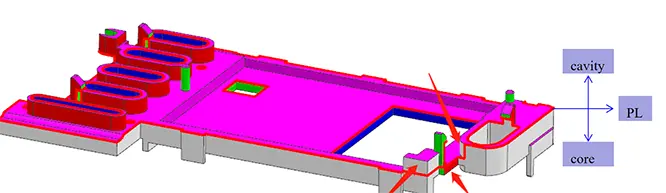
① Determine the Mold-Release Direction
Determine the primary mold-release direction based on the core and cavity orientation.
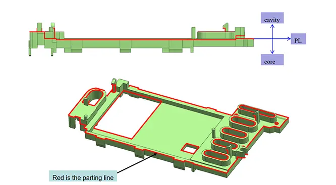
② Identify All Surfaces Parallel to the Mold-Release Direction
Draft analysis shows that the green areas in the figure—including snap features, bosses, and sidewalls—are essentially parallel to the mold-release direction and do not have sufficient draft.
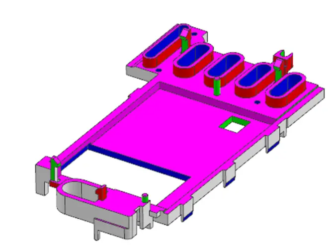
③ Determine the Initial Draft Angle Based on Feature Depth
Based on the dimensions in this example, the following draft angles are obtained:
| Part Feature | Draft Height H | Recommended Draft Angle | One-Sided Dimensional Offset X |
| Square-hole sidewall | 5 mm | 1° | Approx. 0.09 mm |
| Boss | 15 mm | 0.5° | Approx. 0.13 mm |
| Snap-fit sidewall | 18 mm | 2° | Approx. 0.63 mm |
④ Adjust the Angle According to Surface Texture
The surface of this part is a standard smooth finish with no texture, so no additional draft is required for texture release.
⑤ Final Confirmation Through DFM
For special features such as snap fits and bosses, the angle should also be adjusted according to dimensional tolerances and the ejection method. The final manufacturable draft angle is then confirmed through DFM review.
FAQ
Q1: Can a 0° Draft Angle Be Used?
Yes, but it is generally not recommended as a standard design practice. Some mating or functional surfaces may require 0° draft. In such cases, mold polishing, material, feature depth, and the ejection structure should be evaluated separately.
Q2: Who Is Responsible for Designing the Draft Angle?
Typically, the product designer adds the basic draft angle to the part first. The mold engineer then reviews and adjusts it during DFM based on the material, mold structure, and production conditions.
Q3: Is a Larger Draft Angle Always Better?
No. A larger draft angle generally improves mold release, but it also changes part dimensions, appearance, and assembly relationships. The appropriate angle should be selected while still meeting the required mold-release conditions.
Q4: Do Both Inner and Outer Walls Need Draft Angles?
Usually, yes. Any surface that is essentially parallel to the mold-release direction should be checked for draft, especially internal sidewalls that tend to grip tightly around the core.
Q5: Do Textured Surfaces Always Require More Draft?
Usually, yes. The deeper the texture, the greater the release resistance, so textured surfaces generally require larger draft angles than smooth surfaces. The final angle should be confirmed according to the actual texture depth.