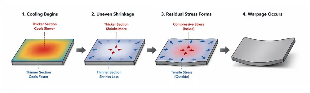
Warpage is a common dimensional defect in injection molding. It usually appears as bending, twisting, lifted corners, or a part that continues to deform after ejection. At its core, warpage happens because different areas of the molded part shrink differently during cooling.
This article focuses on how to identify the source of the problem: whether it comes from part design, mold and processing conditions, or the material itself.
How to Quickly Identify the Cause of Warpage
When a molded part warps, it is usually not wise to start by changing process parameters blindly. The way the part deforms often gives a useful first clue about where to look.
| Warpage Symptom | Check First |
| Long edge bends | Wall thickness uniformity |
| Local twisting | Gate location and material flow direction |
| Four corners lift | Cooling balance in the mold |
| Part keeps deforming after ejection | Cooling time and ejection timing |
| Warpage starts after a material change | Shrinkage rate and glass fiber orientation |
This table does not give the final answer, but it helps narrow the search. In many cases, first deciding whether the issue is more likely related to design, mold, material, or process saves more time than adjusting parameters for several days.
Part Design Factors
Part design often sets the upper limit for warpage risk. If the structure itself tends to create uneven shrinkage, process changes may improve the result, but they rarely remove the problem completely.
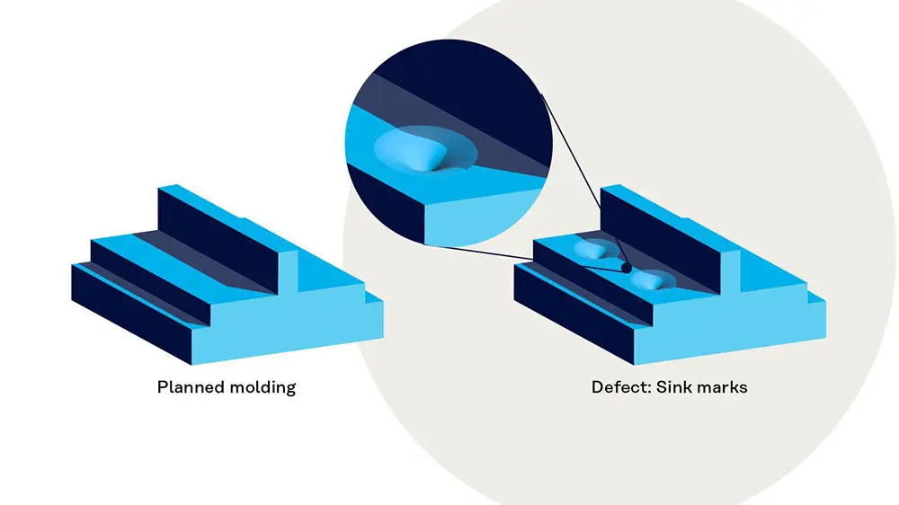
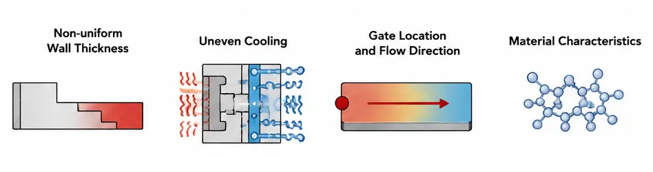
Non-uniform Wall Thickness
Non-uniform wall thickness is one of the most common design-related causes of warpage.
The real problem is not simply that one area is thick. The problem is a sudden thickness change. For example, if the main wall is 2 mm and one local area suddenly increases to 5 mm, the thick section cools more slowly and continues shrinking for longer. After ejection, that difference can show up as bending or distortion.
Large Flat Surfaces
Large flat surfaces are very sensitive to small shrinkage differences.
A 0.2 mm distortion may be almost invisible on a small component. On a housing, trim panel, cover, or large flat plate, the same amount of movement can become a visible bend. For large molded parts, filling the cavity is not enough; dimensional stability must be considered from the beginning.
Insufficient Structural Support
Some parts have reasonably uniform wall thickness and still warp.
In those cases, the problem may be low overall stiffness. Large thin-wall structures are more likely to be pulled out of shape by residual stress after ejection. However, adding more ribs is not automatically the answer. Too many or poorly designed ribs can create new thick areas and new shrinkage differences.
In addition, if slight warpage cannot be fully avoided in large flat or thin-wall structures, the design can include reasonable assembly tolerance. Positioning features, snap fits, or screw bosses can also be used to control critical assembly areas, so minor deformation does not affect the final fit or functional performance.
Mold and Process Factors
If part design sets the warpage risk, mold and process conditions determine whether that risk becomes worse in production.
Cooling System
Warpage is not caused only by slow cooling. More often, it is caused by uneven cooling.
If one area of the mold removes heat much more slowly than the surrounding areas, that section stays hot for longer and shrinks more after other areas have already stabilized. When warpage repeats in the same location, the cooling layout should be checked early.
Gate Location
Gate location affects more than filling. It also affects how the part shrinks.
For long parts, thin-wall parts, and glass-filled materials, the gate position can strongly influence material flow direction and final deformation. In some cases, several days of process adjustment will do little, while a better gate location can make a much bigger difference.
Packing Pressure and Packing Time
Packing pressure is not a simple “higher is better” setting. During packing, additional melt is pushed into the cavity as the material starts to shrink, helping the part hold a more stable size.
Whether higher packing helps depends on the real source of the warpage. If the problem comes from wall thickness variation, poor cooling balance, or material orientation, increasing packing pressure or packing time may have only a limited effect.
Cooling Time
Cooling time is one of the easiest parameters to reduce during mass production.
A part may look fine during trial molding, then start to warp after production speed is increased. In many cases, the mold has not suddenly become worse; the cycle has simply been shortened. If the part is ejected before the inside is stable, shrinkage continues outside the mold.
Ejection Timing
A part that looks flat at ejection is not always stable.
If the part is ejected too early, the internal temperature can still be high. Once the part leaves the mold, it continues to shrink without mold support. Many “it looked fine at first, then bent later” problems are related to early ejection or insufficient cooling.
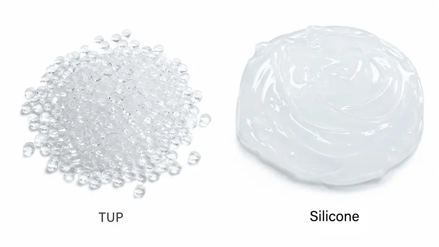
Material Factors
With the same mold and the same process, changing the material can completely change the warpage behavior.
Crystalline and Amorphous Plastics
Crystalline plastics such as PP, PE, and PA usually have higher shrinkage and are more prone to warpage. Amorphous plastics such as ABS and PC generally shrink more consistently and are often easier to control dimensionally.
That is why the same part may warp with PP but behave much better with ABS. This does not mean ABS is always the better choice. Material selection must also consider cost, strength, temperature resistance, chemical resistance, and the actual service environment.
Glass Fiber Reinforced Materials
Many people assume that adding glass fiber makes the material stiffer, so the part should warp less.
In reality, it is not that simple. Glass fibers tend to align with the melt flow direction. Because shrinkage differs along and across the fiber direction, anisotropic shrinkage becomes a major reason why PA+GF and PBT+GF parts can twist or deform.
For a deeper technical explanation, see this reference on glass fiber orientation and its effect on reinforced plastic parts.
Warpage Tendency of Common Materials
| Material | Warpage Tendency |
| PP | High |
| PE | High |
| PA | High |
| ABS | Medium |
| PC | Low |
| PC/ABS | Low |
| PA+GF | Medium to high |
This table should only be used as a general guide. The real risk depends on whether the material shrinkage behavior matches the part structure, mold cooling, and gate location.
Frequently Asked Questions
Why does increasing packing pressure sometimes have little effect on warpage?
Because packing can only influence part of the compensation and shrinkage process. It cannot change part geometry, cooling layout, or the inherent shrinkage behavior of the material. If the real issue is wall thickness variation, uneven cooling, or fiber orientation, more packing pressure usually has limited value.
Is warpage mainly a design issue or a process issue?
It can be either. If the part always deforms in the same location, part design and mold cooling should be checked first. If the amount of warpage changes noticeably when process settings change, process control is also part of the problem.
Can a hot runner system reduce warpage?
Sometimes. A hot runner can improve melt flow and pressure transfer, which may help some parts shrink more evenly. However, if the part has large wall thickness changes or the cooling condition is not balanced, a hot runner will not eliminate warpage by itself.