
There is no universal standard for wall thickness in injection molded parts. Walls that are too thick can lead to sink marks, voids, and longer cycle times, while walls that are too thin may cause short shots, insufficient rigidity, and deformation during ejection. This article explains wall thickness design rules from four perspectives—mechanical performance, moldability, appearance, and cost—and demonstrates practical optimization methods using common structural features.
1. How Thick Should an Injection Molded Part Be?
There is no fixed wall thickness for plastic parts. The appropriate thickness should be determined based on the material, part size, geometry, and functional requirements. For thermoplastics, the typical wall thickness ranges from 0.5 to 4 mm, with 2–3 mm being the most commonly used. If additional stiffness is required, it is generally better to improve the structure by adding ribs, curved surfaces, or flanges instead of simply increasing the overall wall thickness.
The table below shows the recommended wall thickness ranges for common injection molding materials.
| Plastic Material | Minimum Wall Thickness (mm) | Small Parts (mm) | Medium Parts (mm) | Large Parts (mm) |
| PA | 0.45 | 0.76 | 1.50 | 2.40–3.20 |
| PE | 0.60 | 1.25 | 1.60 | 2.40–3.20 |
| PS | 0.75 | 1.25 | 1.60 | 3.20–5.40 |
| PMMA | 0.80 | 1.50 | 2.20 | 4.00–6.50 |
| PP | 0.85 | 1.45 | 1.75 | 2.40–3.20 |
| PC | 0.95 | 1.80 | 2.30 | 3.00–4.50 |
| POM | 0.80 | 1.40 | 1.60 | 2.40–3.20 |
| PPO | 1.20 | 1.75 | 2.50 | 3.50–6.40 |
| ABS | 0.80 | 1.50 | 2.20 | 2.40–3.20 |
| PVC | 1.15 | 1.60 | 1.80 | 3.20–5.80 |
These recommended values are conservative guidelines only. In actual applications, the table does not clearly define what qualifies as a small, medium, or large plastic part, so the values should be used as a general reference rather than an absolute rule.
2. Wall Thickness Design Principles
Principle 1: Design Based on Mechanical Performance
Whether the part is an external housing or an internal component, it must have sufficient strength. Even before considering other factors, the part should at least be strong enough to withstand the ejection force during molding. If the wall is too thin, the part can easily deform during ejection.
In general, increasing wall thickness improves stiffness and load-bearing capacity when all other conditions remain the same. However, once the wall exceeds a certain thickness, defects such as sink marks, shrinkage voids, or internal voids become more likely. Ironically, these defects may actually reduce the part’s strength. At the same time, the part becomes heavier, material consumption increases, and the injection molding cycle becomes longer.
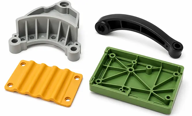
Obviously, simply making a plastic part thicker is not the best way to improve its strength. A better approach is to increase rigidity through geometric features such as ribs, curved surfaces, corrugations, and reinforcing structures.
Principle 2: Design Based on Moldability
Of course, some parts are restricted by available space, and wall thickness may be the primary means of achieving the required strength. In such cases, if strength is a key design consideration, I recommend determining the wall thickness based on moldability.
So how do you evaluate moldability?
① Understand melt flow behavior and melt flow index.
Materials with lower flowability generally require a greater minimum wall thickness.
Based on mold design requirements, common plastics can be roughly classified into three flowability categories:
Good flowability: PA, PE, PS, PP, CA
Medium flowability: Styrene-based resins (such as ABS and AS), PMMA, POM
Poor flowability: PC, rigid PVC, PPO, PSF, PASF, fluoroplastics
(This classification only reflects the general processing characteristics of some unfilled standard grades and should not replace the technical data sheet for a specific material grade.)
② Wall thickness can also be determined using the flow length-to-thickness ratio, as shown below:
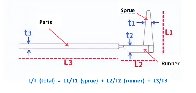
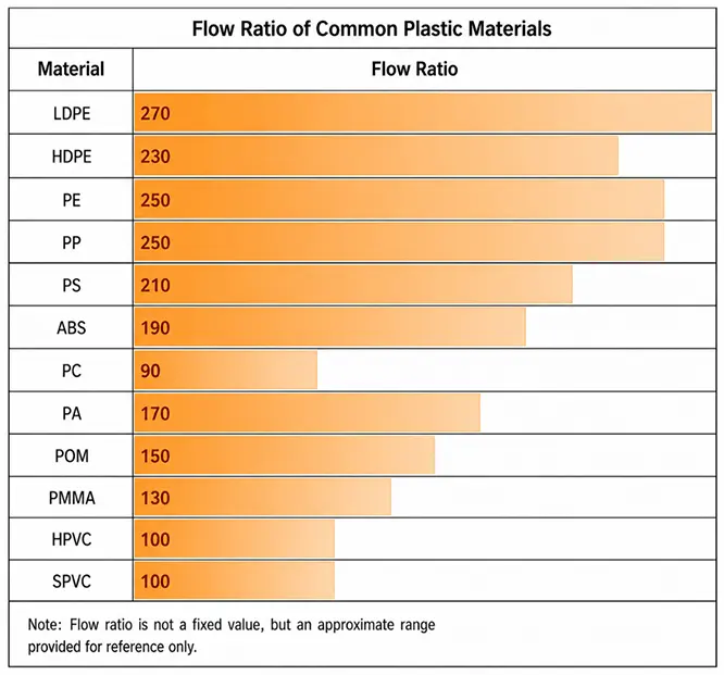
If the calculated flow length ratio exceeds the recommended value, molding becomes more difficult. Higher injection speed and injection pressure may be required, and in some cases, specialized high-performance injection molding equipment may be necessary. Another solution is to add more gates, although this will increase mold cost.
Principle 3: Design Based on Appearance
Wall thickness affects the appearance of molded parts in several ways.
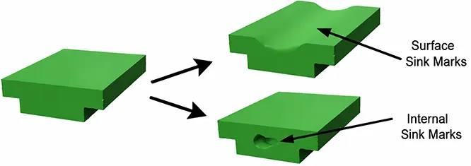
① Walls that are too thick: sink marks and internal voids
In thick-wall areas, the material near the mold surface cools quickly, while the material at the center cools much more slowly. As the inner material continues to shrink during cooling, insufficient packing pressure may lead to internal voids, or it may pull the already solidified surface inward, resulting in visible sink marks.
② Walls that are too thin: short shots, ejector pin marks, and warpage
Thin walls increase flow resistance, making it more difficult for the molten plastic to completely fill the cavity, which can lead to short shots. At the same time, insufficient rigidity makes the part more susceptible to deformation during ejection or leaves obvious ejector pin marks. Uneven shrinkage during cooling may also cause warpage. In general, the wall thickness should not be lower than the recommended value for the selected material and part size.
③ Non-uniform wall thickness: sink marks (including read-through, depressions, and thick-to-thin transition marks), warpage, and other defects
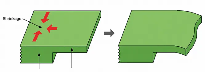
When changes in wall thickness cannot be avoided, the transition should be gradual, as shown below.
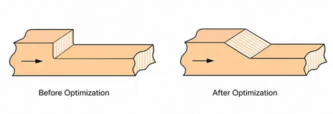
Based on my own experience, I generally recommend maintaining an average housing wall thickness greater than 1.2 mm, while the perimeter walls should preferably be thicker than 1.4 mm. Wall thickness transitions should not be too drastic. When changing from thin to thick, the thickness should not exceed 2.0 times the original wall. When changing from thick to thin, the thinner section should not be less than 50% of the original wall thickness. Rib thickness should also remain below 75% of the nominal wall thickness.
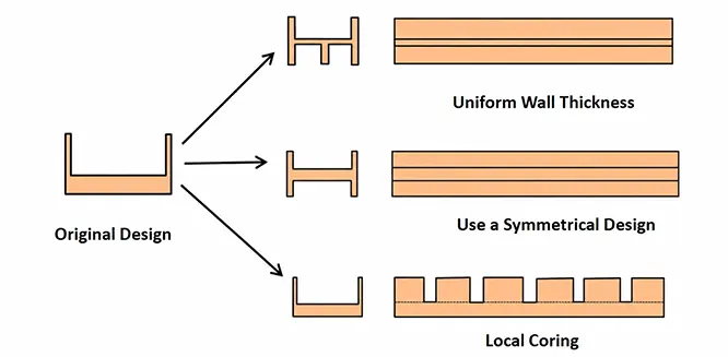
Of course, achieving perfectly uniform wall thickness is not always possible, especially for complex parts. Even so, many of the resulting issues can be minimized through proper structural design, as shown below.
Principle 4: Design Based on Cost
Excessive wall thickness wastes raw material, but that’s not even the biggest concern. The more significant issue is the longer cooling time, which directly extends the entire injection molding cycle, reduces production efficiency, and ultimately increases part cost.
The table below shows the approximate cooling time (seconds) for different wall thicknesses of common plastics. These values are for reference only.
| Material | 1.0 mm | 2.0 mm | 3.0 mm | 4.0 mm | 5.0 mm | 6.0 mm |
| ABS | 1.8 | 7.0 | 15.8 | 28.2 | 44.0 | 63.4 |
| CA | 2.2 | 8.8 | 19.9 | 35.4 | 55.3 | 79.6 |
| CAB | 2.1 | 8.2 | 18.5 | 32.8 | 51.3 | 73.8 |
| PA6 | 1.5 | 5.8 | 13.1 | 23.2 | 36.3 | 52.2 |
| PA66 | 1.6 | 6.4 | 14.4 | 25.6 | 40.0 | 57.6 |
| PC | 2.1 | 8.2 | 18.5 | 32.8 | 51.5 | 74.2 |
| PE-HD | 2.9 | 11.6 | 26.1 | 46.4 | 72.5 | 104.4 |
| PEI | 1.7 | 7.2 | 16.1 | 27.7 | 43.4 | 62.3 |
| PE-LD | 3.2 | 12.6 | 28.4 | 50.1 | 79.0 | 113.8 |
| PES | 2.6 | 10.4 | 23.3 | 41.4 | 64.8 | 93.2 |
| PMMA | 2.3 | 9.0 | 20.3 | 36.2 | 56.5 | 81.4 |
| POM-CO | 1.9 | 7.7 | 17.3 | 30.7 | 48.0 | 69.2 |
| PP | 2.5 | 9.9 | 22.3 | 39.5 | 61.8 | 88.9 |
| PS | 1.3 | 5.4 | 12.1 | 21.4 | 33.5 | 48.4 |
| HIPS | 1.3 | 5.4 | 12.1 | 21.4 | 33.5 | 48.4 |
| PPO-M | 1.4 | 5.6 | 12.6 | 22.4 | 35.0 | 50.4 |
| PPVC | 2.2 | 8.9 | 20.1 | 35.7 | 55.8 | 80.3 |
| PSU | 2.6 | 10.4 | 23.3 | 41.4 | 64.8 | 93.2 |
| SAN | 2.1 | 8.4 | 18.9 | 33.6 | 52.9 | 75.6 |
| UPVC | 2.7 | 10.7 | 24.2 | 43.0 | 67.3 | 96.8 |
3. Best Practices for Injection Molded Part Wall Thickness Design
In addition to the design principles discussed above, the following techniques are widely used to optimize wall thickness.
Core Out Solid Bosses and Standoffs
Solid bosses and standoffs often overlap with the base wall, creating localized thick sections. Coring them out so that their wall thickness is close to the nominal wall thickness helps reduce sink marks, internal voids, and uneven cooling.

Make the Inner Contour Follow the Outer Shape
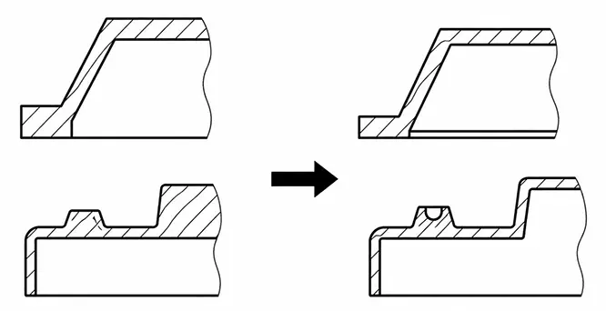
When the exterior includes slopes, steps, or raised features, the inner contour should be modified accordingly. Otherwise, the exterior shape changes may create hidden thick-wall sections inside the part.
Use Ribs Instead of Thickening the Entire Wall
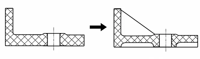
Simply thickening corners or connection areas often creates localized thick sections, increasing the risk of sink marks and uneven cooling. A better solution is to maintain a relatively uniform nominal wall thickness while adding reinforcing ribs or triangular gussets to improve stiffness.
FAQ
Q1: If the wall thickness is below the recommended value for the material, does that mean the part cannot be injection molded?
Not necessarily. The recommended values are general design guidelines. Thin-wall parts can still be molded successfully, but factors such as material flowability, flow length, gate location, and machine capability need to be evaluated carefully.
Q2: If I switch to a different plastic material, can I keep the original wall thickness?
Not necessarily. Different materials have different flow characteristics, shrinkage rates, and mechanical properties. Whenever the material changes, the wall thickness, gate design, and reinforcing features should all be reassessed.
Q3: Is mold flow analysis necessary after the wall thickness has been finalized?
Not always. For simple parts with straightforward geometry, mold flow analysis may not be required. However, for thin-wall parts, large components, long flow paths, or designs with significant wall thickness variations, mold flow analysis can identify potential risks such as short shots, sink marks, and warpage before tooling begins.
Q4: What should be considered when designing wall thickness for parts with high cosmetic requirements?
Bosses and reinforcing ribs behind cosmetic surfaces should not create localized thick sections. The boss wall thickness, rib base thickness, and connection design all need to be carefully controlled; otherwise, sink marks or visible depressions may appear on the visible surface.
Q5: Does wall thickness affect gate location?
Yes. Thin-wall regions or areas located far from the gate are more difficult to fill. The gate should be positioned to minimize the melt flow distance and prevent thin-wall sections from becoming the last areas to fill.