During ejection, an injection-molded part must overcome the gripping force caused by material shrinkage, friction between the part and the mold, and vacuum suction in deep-cavity or semi-enclosed geometries. To ensure smooth part release and stable mold operation, different ejection mechanisms are used according to the part design. Below, we will look at common ejection methods, their suitable applications, selection criteria, key design factors, and typical problems.
1. Common Mechanical Ejection Methods
Ejector Pin Ejection (Round Ejector Pins)
Working Principle:
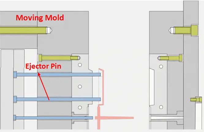
After the mold opens, the part remains on the core on the moving half of the mold. The injection molding machine’s ejector rod pushes the ejector plates forward, driving the ejector pins to remove the part from the core. Once ejection is complete, the pins return to their original position through return pins or springs.
Advantages:
The structure is simple, relatively inexpensive, and easy to maintain. It is the most widely used ejection method in injection molds.
Disadvantages:
Because ejector pins have a relatively small contact area, excessive or uneven ejection force may cause stress whitening, punch-through, deformation, or visible ejector pin marks.
Blade Ejector Ejection
Working Principle:
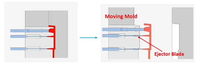
A blade ejector operates in the same way as a standard round ejector pin, but it has a flat cross-section that allows it to push the part from narrow areas. Compared with a thin round pin, a blade ejector provides a larger contact area in confined spaces, helping reduce stress whitening.
Advantages:
It can fit into narrow features, increase the contact length along ribs, and reduce localized ejection pressure.
Disadvantages:
Blade ejectors are generally less rigid than round ejector pins. They also require higher machining and fitting accuracy and may bend, wear, or break if used improperly.
Ejector Sleeve Ejection
Working Principle:
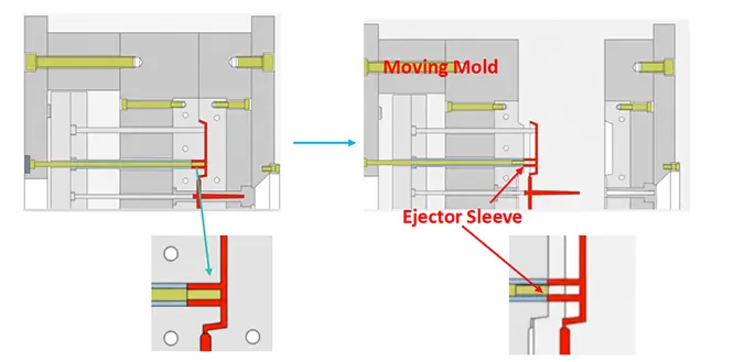
An ejector sleeve is a tubular ejecting component fitted around a central core pin. During ejection, the sleeve moves forward around the cylindrical feature and pushes the part out evenly.
Advantages:
The ejection force is distributed around the circumference of the cylindrical feature, making boss deflection and stress whitening less likely than with a single ejector pin.
Disadvantages:
Ejector sleeves are more complex than standard ejector pins and require greater machining accuracy and proper lubrication. Thin sleeves are also more susceptible to wear or cracking.
Ejector Block Ejection
Working Principle:
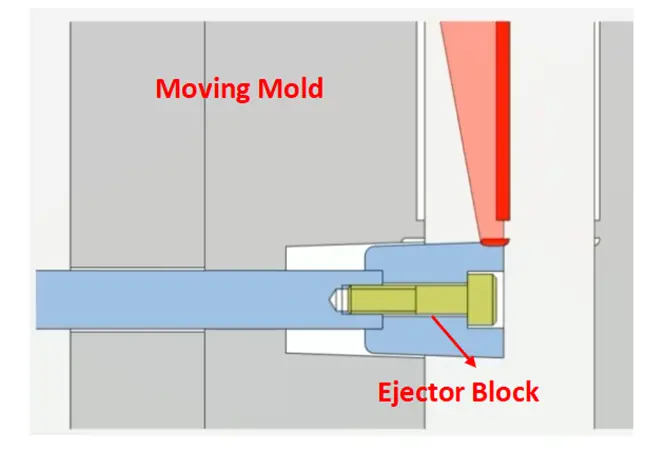
After the mold opens, the ejector plates drive the ejector block forward. Its larger contact surface pushes the part off the core in a stable manner, reducing the risk of deformation caused by concentrated force.
Advantages:
The larger contact area distributes the ejection force more evenly and can reduce stress whitening, punch-through, and localized deformation.
Disadvantages:
Ejector blocks take up more space inside the mold and require accurate machining and fitting. Poor edge clearance may result in flash or visible witness lines.
Stripper Plate Ejection
Working Principle:
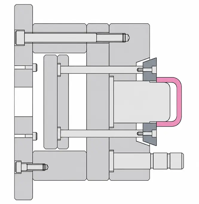
The stripper plate moves forward around the edge of the part or the core, pushing the part out through a continuous annular or broad contact surface.
Advantages:
The large ejection area distributes force evenly, reducing localized deformation and eliminating or minimizing ejector pin marks.
Disadvantages:
The mold structure is more complex and expensive to manufacture. A precise fit must also be maintained between the stripper plate and the core; otherwise, wear or flash may occur.
Air Ejection
Working Principle:
Compressed air is introduced between the part and the core through an air valve or air passage. This breaks the local vacuum and uses air pressure to assist part release.

Advantages:
Air ejection effectively reduces vacuum suction, lowers the mechanical force required for ejection, and helps minimize part deformation.
Disadvantages:
Air ejection is usually an auxiliary method. Many parts still require ejector pins or a stripper plate. Excessive air pressure or poorly designed air passages may cause the part to pop out suddenly or lead to unstable ejection.
2. Undercut Release Methods
Slide Core Release
Working Principle:
As the mold opens, the slide moves laterally under the action of an angle pin, hydraulic cylinder, or another driving mechanism. It first withdraws the side core or releases the external undercut, after which the main ejection system removes the part.
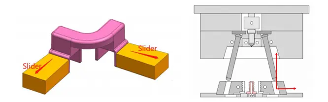
During mold opening, the angled guide pin converts the relative opening movement into leftward or rightward lateral movement of the slide.
Advantages:
Slides can complete side-core pulling automatically. The mechanism is mature and well suited to medium- and high-volume production.
Disadvantages:
Slides increase mold size, cost, and maintenance requirements. The mechanism becomes more complex when a long travel distance or high pulling force is required.
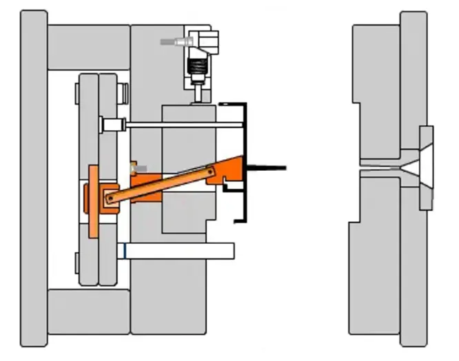
Lifter Demolding
Working Principle:
During ejection, the lifter moves both forward and sideways, gradually withdrawing from the internal undercut.
Advantages:
A lifter combines undercut release and part ejection in a single movement, making the mechanism relatively compact.
Disadvantages:
Lifters are subjected to lateral forces and require accurate fitting and proper lubrication. Poor design may lead to jamming, wear, or Drag Marks of the molded part.
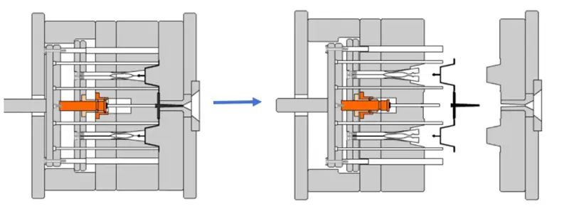
Collapsible Core Demolding
Working Principle:
After the mold opens, the individual segments of the core collapse inward, reducing the core’s outside diameter and releasing it from the part’s internal annular undercut.
Advantages:
A collapsible core can automatically release complex, continuous internal undercuts and is suitable for stable volume production.
Disadvantages:
The mechanism is complex and expensive. It also requires sufficient mold space, high machining accuracy, and careful maintenance.
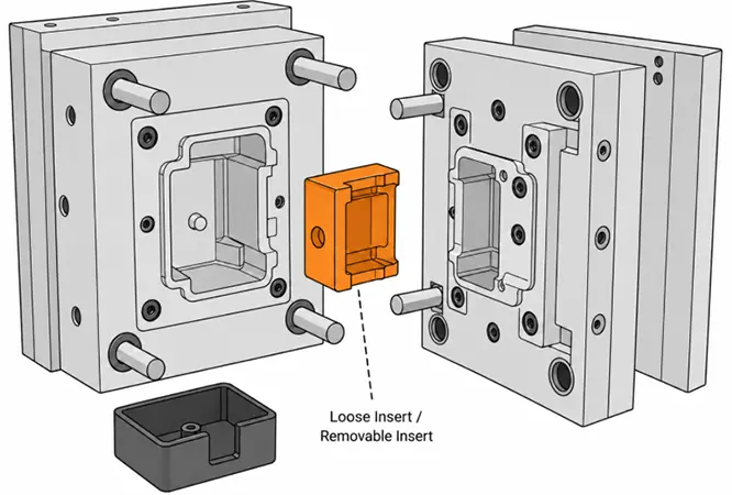
Loose Insert Demolding
Working Principle:
A loose insert forms a local feature of the molded part. After the mold opens, the part and insert are removed together. The insert is then separated manually or with auxiliary equipment, cleaned, and returned to the mold for the next molding cycle.
Advantages:
The structure is relatively simple and has a lower initial tooling cost. It can also handle certain geometries that are difficult to achieve with slides or lifters.
Disadvantages:
Loose inserts usually require manual loading and removal, which extends the molding cycle. There is also a risk of missing, reversing, or incorrectly positioning the insert, making this method unsuitable for highly automated production.
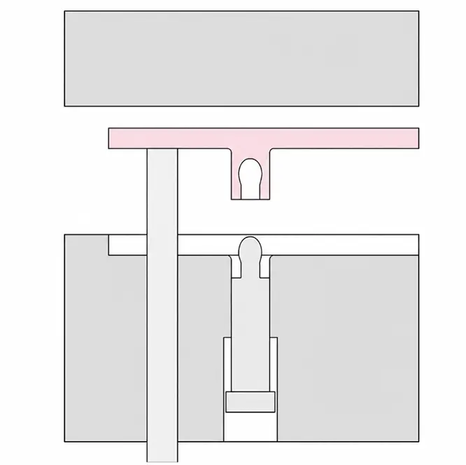
Forced Demolding
Working Principle:
This method uses the elasticity of the plastic material. During ejection, the undercut temporarily deforms and is forced over the core or molded projection.
Advantages:
No slide, lifter, or other complex mechanism is required, which simplifies the mold and reduces cost.
Disadvantages:
The method places strict requirements on material properties, undercut dimensions, and wall thickness. Poor design may cause stress whitening, cracking, permanent deformation, or dimensional instability.
Thread Stripping
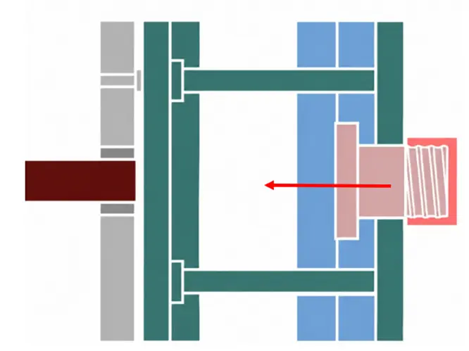
Working Principle:
During ejection, the elasticity of the plastic allows an internal or external molded thread to deform temporarily and pass directly over the threaded core.
Advantages:
The mold structure is simple, the release cycle is fast, and no complex rotary mechanism is required.
Disadvantages:
The threads may deform during stripping. This method is not suitable for deep threads, precision threads, or brittle materials.
Unscrewing
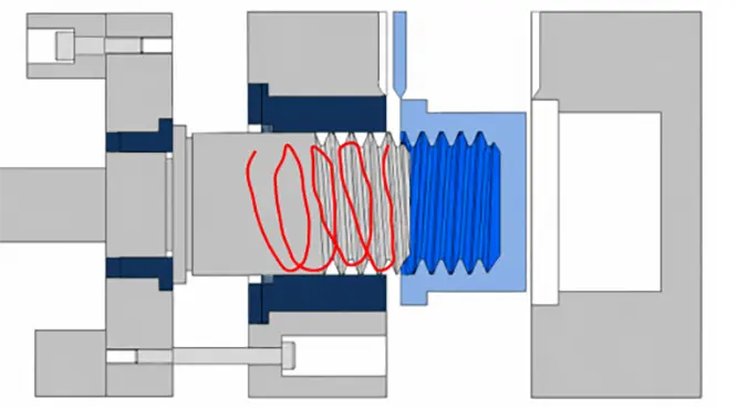
Working Principle:
During mold opening, a gear, rack, hydraulic mechanism, or electric motor rotates the threaded core so that it withdraws from the molded part along the thread path.
Advantages:
Unscrewing protects the thread profile and dimensions, making it suitable for high-volume parts with demanding thread-accuracy requirements.
Disadvantages:
The mold is more complex and expensive, and the unscrewing action may extend the molding cycle.
3. Special and Combined Ejection Methods
Two-Stage Ejection
Working Principle:
The part is released through two consecutive but separate ejection stages. The first stage reduces the gripping force or completes a partial release, while the second stage fully removes the part from the mold.

Advantages:
Two-stage ejection provides better control over the release sequence of different areas, reducing the risk of stretching the part or leaving it trapped on an ejecting component.
Disadvantages:
The mold mechanism and motion control are more complicated. More components are required, which also increases maintenance demands.
A-Side Ejection (Fixed-Half Ejection)
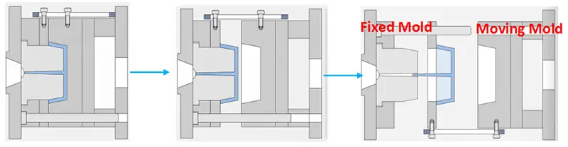
Working Principle:
When the injection molding machine opens the mold, the moving half, or B-side, moves backward. For structural or processing reasons, the part may remain in the fixed half. An ejection mechanism installed between the fixed-side clamping plate and mold plate, such as ejector pins or a stripper plate, then operates to release the part.
Advantages:
A-side ejection accommodates special part-retention requirements and solves situations that cannot be handled by conventional B-side ejection.
Disadvantages:
A-side ejection is generally more complex than conventional B-side ejection and requires precise control of the mold-opening and ejection sequence.
Combined Ejection
Working Principle:
Two or more demolding mechanisms are used in the same mold. Each mechanism releases a different restriction before the part is finally ejected.
Advantages:
Different areas of a complex part can be handled with dedicated release actions, improving overall demolding reliability.
Disadvantages:
The mold structure, motion sequence, and maintenance requirements become more complex. Poorly coordinated mechanisms may interfere with one another.
Common combinations include:
Lifters and ejector pins
Stripper plates and air ejection
Slides, lifters, and ejector blocks
Unscrewing mechanisms and stripper plates
4. How to Choose the Right Ejection Method
No ejection method is universally better than another. The appropriate solution depends on the part geometry, material, cosmetic requirements, and production volume.
| Part Feature | Recommended Method |
| Standard flat parts or housings | Ejector pins or ejector blocks |
| Narrow, deep ribs | Blade ejectors |
| Screw bosses | Ejector sleeves |
| Thin-walled cylindrical parts or caps | Stripper plates |
| Side holes or external undercuts | Slides |
| Local internal undercuts | Lifters |
| Annular internal undercuts | Collapsible cores or forced demolding |
| Complex, low-volume parts | Loose inserts |
| Shallow plastic threads | Thread stripping |
| Deep or precision threads | Automatic unscrewing |
In actual mold design, one part may require several release methods. For example, a housing with a side hole and an internal snap-fit may first use a slide to release the side hole, followed by a lifter to clear the internal undercut, and finally ejector pins to remove the part.
5. Case Study — Demolding with a Loose Insert
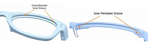
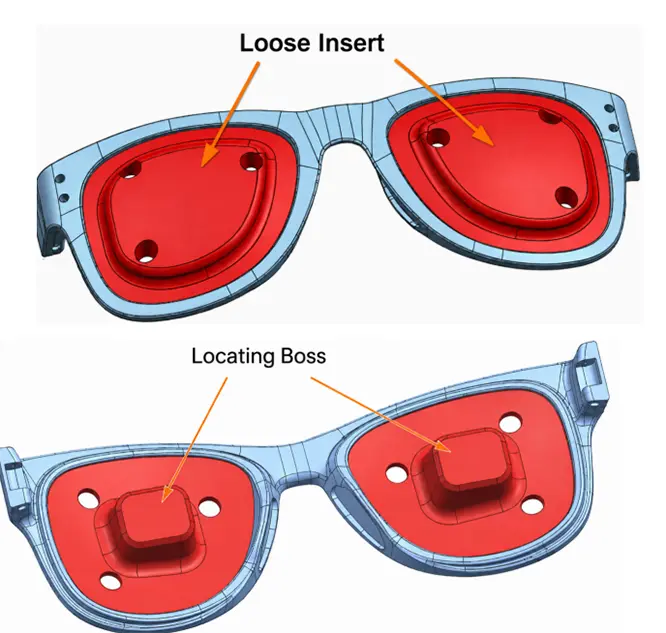
As shown above, this eyeglass frame has a continuous internal groove around the lens rim. In this case, the undercut cannot be released using sliders. Given the extremely limited space, it would also be impractical to use several angled lifters moving in different directions. Forced demolding would inevitably scratch or damage the molded part.
The solution is to place a loose insert inside the lens rim and eject it together with the molded part. The loose insert is loaded into the mold before mold closing and is then ejected together with the part during mold opening.
Loose inserts generally require reliable positioning. As shown in the figure below, locating bosses should be added to keep the insert securely in the correct position.
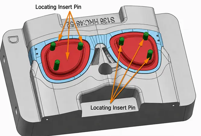
However, locating bosses alone are not sufficient. Locating pins must also be added to retain the insert. Without these pins, the insert may tilt outward, fall out, or become loose, creating a risk of being trapped and crushed when the mold closes. The locating pins hold the insert in place and prevent it from falling or shifting.
6. Design Factors That Affect Ejection
Draft Angle
An appropriate draft angle reduces friction between the molded part and the mold. Deeper cavities and more heavily textured surfaces generally require greater draft. A typical range is 0.5° to 3°, although the actual value should be adjusted according to the material, part geometry, and surface finish.
Plastic Shrinkage and Material Flexibility
Plastic shrinks as it cools and may grip the core tightly. Materials with higher shrinkage or greater rigidity generally require more ejection force, while flexible materials may permit a certain degree of forced demolding.
Areas of Core Gripping
Parts commonly grip the mold around cores, deep ribs, bosses, and local projections. During mold design, the main gripping areas should be identified so that ejecting components can be positioned nearby.
Ejection Area and Force Distribution
A contact area that is too small, or an uneven distribution of force, can cause stress whitening, punch-through, or deformation. Large or thin-walled parts usually require more ejection points or broader-contact systems such as ejector blocks and stripper plates.
Ejector Marks and Cosmetic Requirements
Ejector pins, sleeves, and blocks can all leave visible marks on a molded surface. For cosmetic parts, ejecting components should be placed on internal surfaces, assembly surfaces, or other inconspicuous areas whenever possible.
7. Common Ejection Problems and Solutions
| Ejection Problem | Common Causes | Basic Solutions |
| Part sticking | Insufficient draft, rough mold surface, excessive gripping force on the core | Increase draft, improve the mold surface, and adjust part retention |
| Stress whitening | Excessive local ejection force or ejector pins that are too small | Increase the contact area and adjust the number and position of ejector pins |
| Punch-through | Insufficient wall thickness, ejector pins that are too small, or excessive ejection speed | Increase local wall thickness, use an ejector block or larger pins, and reduce ejection speed |
| Deformation | Uneven ejection force or insufficient cooling | Distribute ejecting components more evenly and extend the cooling time |
| Drag Marks | Insufficient draft, rough mold surfaces, or unintended undercuts | Increase draft, polish the mold, and inspect the part for undercuts |
| Undercut cracking | Excessive forced-demolding depth or insufficient material flexibility | Reduce the undercut, add suitable radii, or use a slide or lifter |
| Ejector pin marks | Excessive pin pressure or insufficient wall thickness at the ejector location | Add more ejector pins, reduce localized pressure, and move pins to stronger areas |
| Thread damage | Excessive thread depth during stripping, unsuitable thread profile, or material that is too rigid | Optimize the thread profile, reduce thread depth, or use an unscrewing mechanism |
Conclusion
Based on our project experience, ejection issues are best addressed during the early stages of part and mold design rather than through repeated modifications after mold trials. The ejection solution should account not only for part geometry, but also for material shrinkage, cosmetic requirements, production volume, and automation needs. In general, simpler mechanisms and more evenly distributed forces result in more reliable molds and lower long-term maintenance costs.