
A lip-and-groove joint is a common mating feature used in plastic assemblies. It mainly provides alignment, positioning, and seam control between upper and lower housings, while also helping with dust protection, light blocking, and sealing. This article covers common lip-and-groove configurations, their functions, dimensional design, and key design considerations.
1. Common Types of Lip-and-Groove Features in Plastic Parts
1) Single Lip and Groove
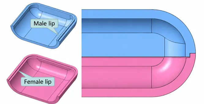
A single lip-and-groove is the most common configuration and consists of a male lip and a female groove. In cross-section, the two form a matching protrusion and recess: the raised feature added along the inside edge of a sidewall is the male lip, while the recessed feature cut into the inside edge is the female groove. In general, the male lip is placed on the thinner housing wall, while the female groove is placed on the thicker wall.
2) Double Lip and Groove
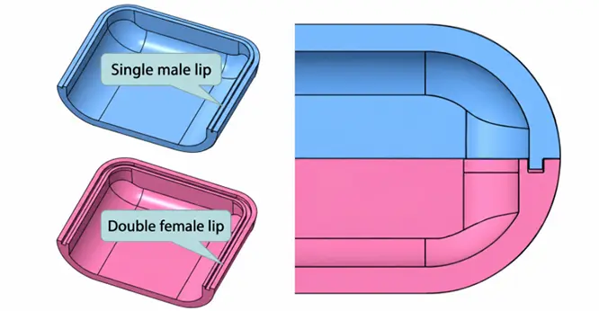
Single male lip + double female groove: This configuration is mainly used when the housing walls are relatively thin but the visible step or mismatch at the seam must be tightly controlled. The double female groove on the lower housing helps limit both inward and outward deformation of the upper housing.
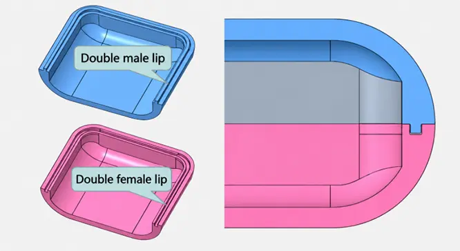
Double male lip + double female groove: This configuration is mainly used when both the upper and lower housings have relatively thick walls. It is also commonly used as a sealing lip-and-groove structure. For waterproof applications, a sealing gasket can be added between the two lips, or ultrasonic welding can be used to create a sealed joint.
3) Reverse Lip
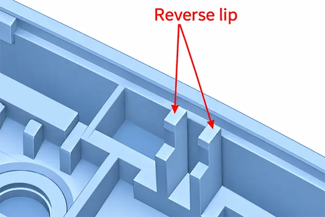
A reverse lip is an additional reverse-facing locating feature added to a conventional lip-and-groove structure. When the wall on the female-groove side is too thin to accommodate a complete double lip-and-groove but additional positioning is still needed in the opposite direction, a reverse lip can be added. Its main purpose is supplemental positioning rather than locking.
2. Main Functions of Lip-and-Groove Features in Plastic Parts
1) Assembly Alignment
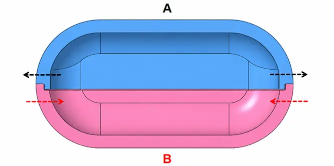
When the male lip enters the female groove, it limits lateral movement between the upper and lower housings and helps the two parts align during assembly.
2) Improved Seam Appearance
A properly designed lip and groove can reduce mismatch and step differences between the upper and lower housings, creating a more uniform seam around the product. This is particularly useful for plastic enclosures with high cosmetic requirements.
3) Dust Protection, Light Blocking, and Auxiliary Sealing
The indirect path created by a lip-and-groove joint helps prevent dust and light from passing directly through the seam. It can also work with gaskets or other sealing features to improve sealing performance.
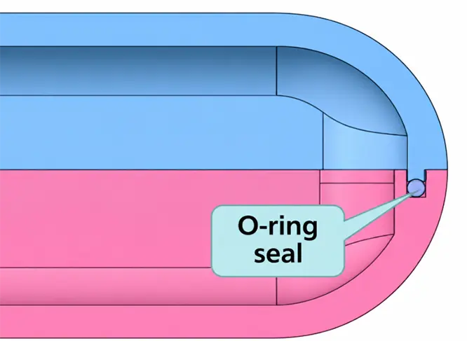
4) Working with Snap-Fits and Screws
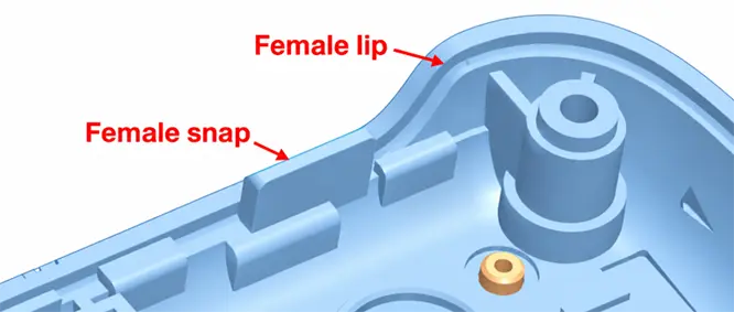
Lip-and-groove features mainly provide alignment and positioning, while snap-fits or screws provide retention and clamping.
The two serve different functions. Even with a lip-and-groove structure, the upper and lower housings may still separate without a suitable locking feature. Conversely, snap-fits alone may not provide sufficient alignment, which can lead to visible seam mismatch.
3. Lip-and-Groove Dimensional Design
The following dimensions can be used as initial references for common plastic enclosure designs. Actual values should be adjusted according to the material, wall thickness, part size, tolerances, and assembly requirements.
1) Male Lip Design
The main dimensions to control in a male lip are its height, root width, draft angle, and top chamfer, as shown below:
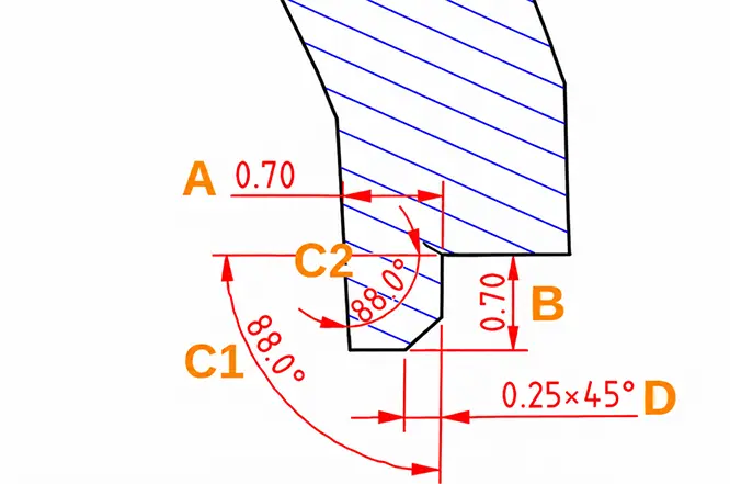
- Height B: 0.60–0.80 mm, providing sufficient basic positioning.
- Root width A: 0.60–0.80 mm. After applying draft, the minimum width at the top should be ≥0.50 mm.
- Draft angles C1 and C2: 2°–3°, helping release the part from the mold and reducing scuffing.
- Top chamferD: 0.25–0.30 mm, providing a lead-in for easier assembly.
2) Lip-and-Groove Fit Design
Lip-and-groove fit design should primarily control the mating clearance, vertical clearance, and local wall thickness:
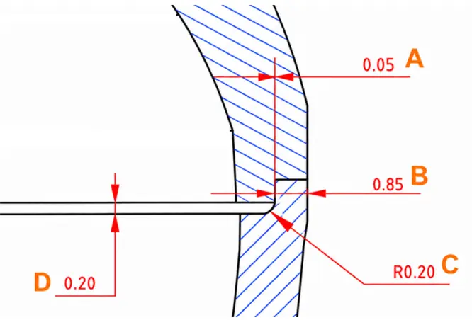
- Mating clearance A: 0.05 mm, used to control the lateral fit between the male lip and female groove.
- Vertical clearance D: 0.10–0.20 mm, with 0.20 mmrecommended, to prevent dimensional variation from causing assembly interference.
- Transition radius C: approximately R0.20 mm, used to smooth abrupt changes in the plastic section. It should not be too large, or it may interfere with assembly.
- Cosmetic-side wall thickness B: ≥0.80 mm, ensuring sufficient strength in the outer housing wall.
3) Reverse Lip Design
Reverse lip design mainly involves controlling its width, height, and assembly chamfer:
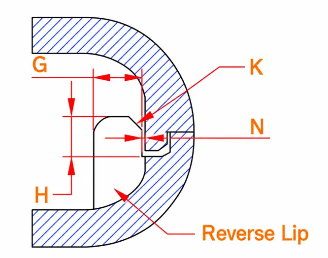
- Width G: Width G: at least equal to the wall thickness, to ensure sufficient strength.
- Height H: typically ≥1 mm. It should not extend too far above the parting line; sufficient effective engagement height after subtracting the chamfer is enough.
- Chamfer K: C0.5–C1.0 mm, providing assembly guidance and reducing interference or collision during assembly.
4) Fit Between the Main Lip and Reverse Lip
When the main lip and reverse lip work together, the key dimensions are the mating clearance, reverse-lip height, and effective engagement length:
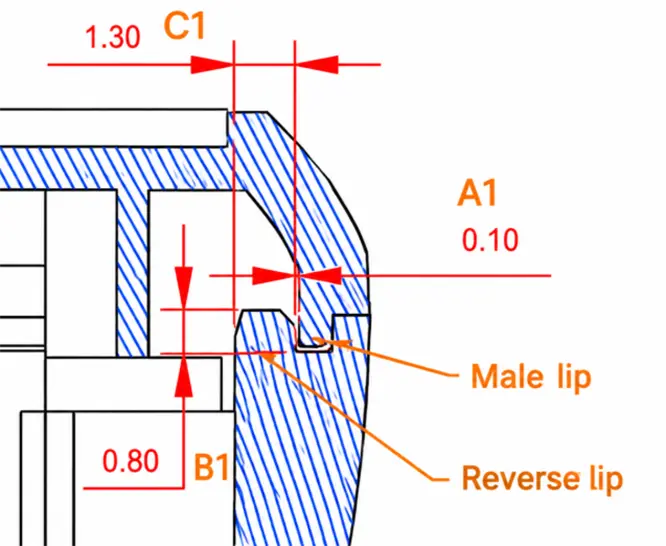
- Mating clearance A1: 0.10 mm, with a maximum of 0.15 mm, to prevent excessive clearance from reducing positioning accuracy.
- Reverse lip heightB1: ≥0.60mm, providing sufficient basic positioning.
- Longitudinal length C1:≥1.00 mm, ensuring adequate effective engagement.
4. Lip-and-Groove Design Principles
1) Wall Thickness and Structural Strength
Lip-and-groove design should first consider whether the housing has sufficient wall thickness.
A male lip that is too thin may deform, short-shot, or even break, while cutting the female groove too deeply can reduce the remaining wall thickness. Double lip-and-groove structures require even more lateral space; if the housing wall is too thin, forcing such a structure into the design may actually reduce part strength.
Local thick sections around the lip root should also be avoided, as they can cause sink marks or localized deformation on the cosmetic surface.
2) Draft and Mold Design
The mold-release direction must be considered when designing lip-and-groove features. The sidewalls of both the male lip and female groove should include suitable draft angles based on the mold-opening direction to reduce scuffing, stress whitening, and sticking during ejection.
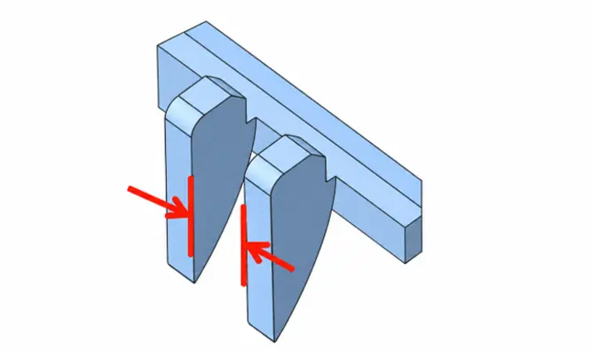
Female grooves and reverse lips should not be designed excessively deep, narrow, or closely spaced. The spacing between adjacent reverse lips is generally recommended to be ≥3 mm, helping prevent thin steel sections in the corresponding mold area that could reduce mold strength, machining stability, and service life.
3) Radii, Chamfers, and Assembly Lead-In
Suitable chamfers or radii should normally be added to the top of the male lip and the entrance of the female groove so that the two parts can guide naturally into position during assembly.
A reasonable radius at the lip root also helps reduce stress concentration and improves melt flow.
However, radii and chamfers should not be too large, as this reduces the effective mating surface and can weaken the locating function of the lip and groove.
4) Tolerance, Assembly, and Appearance Control
A lip-and-groove joint should not be designed with a theoretically perfect zero-clearance fit. Plastic part dimensions are affected by material shrinkage, mold machining tolerances, molding conditions, temperature changes, and other factors, so appropriate assembly clearance must be provided.
The position of the lip and groove should also be coordinated with snap-fits, bosses, and visible seams. Even when the lip-and-groove dimensions are correct, poorly distributed locking points can still cause local seam opening or inconsistent step height.
5. Common Lip-and-Groove Design Problems
| Design Problem | Possible Consequence |
| Male lip and female groove fit too tightly | Difficult assembly, housing deformation, or failure to close completely |
| Excessive mating clearance | Poor positioning, housing movement, or visible mismatch |
| Male lip too thin | Short shots, deformation, or damage during assembly |
| Lip root too thick | Sink marks on the cosmetic surface and uneven cooling |
| Female groove too deep | Insufficient remaining wall thickness and reduced housing strength |
| Insufficient draft | Part scuffing, difficult ejection, and increased mold wear |
| Lip bottoms out too early | Upper and lower housings cannot fully close, resulting in abnormal seam gaps |
| Interference between the lip and snap-fit | Increased assembly resistance or failure of the snap-fit to engage properly |
| Double lip-and-groove used on an overly thin housing | Insufficient remaining wall thickness and reduced structural reliability |
6. Case Study—Clearance Between Snap-Fit and Lip
As shown below, when a snap-fit is positioned close to the housing sidewall, the male lip may interfere with the snap-fit structure. In this case, the male lip on both sides of the snap-fit should be locally removed to provide enough space for snap-fit deflection and assembly.
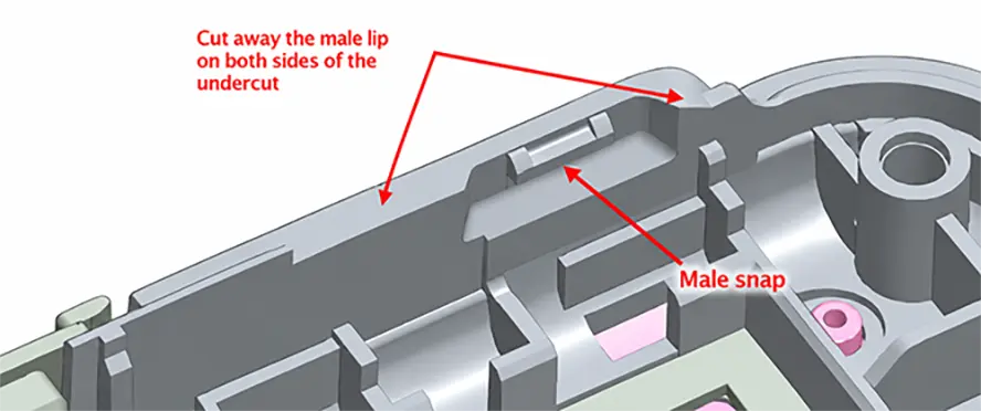
This approach preserves the positioning function of the lip while preventing it from restricting snap-fit deflection, which could otherwise cause difficult engagement or incomplete assembly. The key point is that lip-and-groove features should not simply run continuously around the housing; local relief should be provided where required by snap-fits, screw bosses, and other nearby features.
FAQ
Q1: Can a lip-and-groove joint completely replace snap-fits?
No. Lip-and-groove features mainly provide alignment and positioning and usually cannot provide sufficient axial retention on their own.
Q2: Do all plastic enclosures need a lip-and-groove feature?
Not necessarily. Whether one is needed depends on the required assembly accuracy, structural design, seam appearance, and sealing requirements.
Q3: Does a lip-and-groove feature have to run around the entire enclosure?
No. If the main purpose is local positioning, it can be added only in critical areas.
Q4: Can the same lip-and-groove clearance be used for different plastic materials?
It is not recommended to apply the same value directly. Different plastics have different shrinkage rates, stiffness, and moisture absorption, so the mating clearance should be adjusted accordingly.
Q5: Can lip-and-groove features be designed on curved housings?
Yes. However, curved lip-and-groove features place higher demands on dimensional consistency and mold machining, and the draft direction and assembly path require particular attention.