
During injection molding, black or brown burn marks may sometimes appear on the surface of plastic parts. These defects not only affect appearance but, in more severe cases, may also indicate material degradation. Solving burn mark problems is not simply a matter of lowering the temperature. The key is to identify the actual cause based on where the burn marks appear.
1. What Are Burn Marks in Injection Molding?
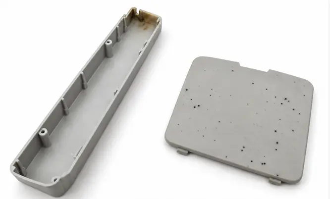
Injection molding burn marks typically appear as black or brown scorch marks or localized discoloration. They are commonly found at the end of fill, in deep ribs, dead-end areas, around weld lines, and near the gate. Burn marks are not necessarily caused by excessive melt temperature; trapped air, insufficient venting, and localized overheating can also be responsible.
Burn Marks are different from Black Spots. Burn Marks usually appear in consistent locations, while Black Spots tend to occur randomly and are more often associated with material degradation, contamination, or carbon buildup inside the molding equipment.
2. What Are the Main Causes of Injection Molding Burn Marks?
1) Trapped Air and Insufficient Venting
This is one of the most common causes of injection molding burn marks. As the melt fills the cavity, air trapped at the end of fill, in deep ribs, dead-end areas, or enclosed sections may not escape quickly enough. The trapped air is rapidly compressed and heated, causing the surrounding plastic to scorch. This phenomenon is also known as the diesel effect.
2) Excessive Injection Speed
Excessive injection speed reduces the time available for air to escape. This becomes especially problematic near the end of filling, when the remaining air can be compressed very quickly, creating localized heat and burn marks.
3) Excessive Melt Temperature
If the barrel, nozzle, or hot runner temperature is too high, the plastic may begin to thermally degrade, resulting in brown or black scorch marks or localized discoloration. Heat-sensitive materials are particularly vulnerable to this problem.
4) Excessive Shear Heating
When molten plastic passes at high speed through a narrow gate, runner, or thin-wall section, significant shear can be generated, producing additional heat. If the localized temperature exceeds what the material can tolerate, burn marks may develop. High screw speed and excessive back pressure can also increase shear heating.
5) Excessive Material Residence Time
Plastic that remains in a hot barrel or hot runner for too long will gradually degrade. For example, an injection molding machine that is much larger than the required shot size, excessively long production cycles, or prolonged machine stoppages can keep the material exposed to heat for too long and generate degraded or carbonized material.
6) Material Contamination or Carbon Buildup
Contaminated raw material, or degraded residue and carbon deposits inside the barrel, nozzle, or hot runner, can also cause black spots, black streaks, or burn-like defects. Unlike burn marks caused by trapped air, these defects are generally not fixed in one location and are more likely to appear randomly.
3. Identifying the Cause by Burn Mark Location
The location of a burn mark can often help narrow down the possible cause quickly.
| Burn Mark Location | More Likely Cause | What to Check First |
| End of fill | Trapped air, insufficient venting | Vents, last-to-fill area, end-stage injection speed |
| Bottom of deep ribs | Localized trapped air | Rib venting, ejector pin or insert venting |
| Dead-end areas or blind cavities | Air cannot escape | Part geometry, vent location |
| Near weld lines | Air trapped where two melt fronts meet | Flow path, localized venting |
| Near the gate | Excessive shear heating | Gate size, injection speed |
| Random black spots or streaks | Material degradation, contamination, or carbon buildup | Raw material, barrel, nozzle, hot runner |
| Only one cavity is affected | Localized mold issue | Venting, gate, and flow conditions in that cavity |
4. How to Fix Injection Molding Burn Marks
1) Improve Venting and Reduce Trapped Air
If burn marks occur at the end of fill, in deep ribs, dead-end areas, or blind cavities, venting in those areas should be checked first.
Start by inspecting and cleaning the existing vents. If the venting capacity is still insufficient, additional vent grooves can be added at the last-to-fill locations, or ejector pins and insert clearances can be used for auxiliary venting. When trapped air is being compressed rapidly near the end of filling, reducing the end-stage injection speed can also give the air more time to escape.
2) Optimize Injection Speed
If burn marks become noticeably worse during high-speed filling, a multi-stage injection speed profile can be used.
Maintain sufficient speed during the early stage to complete most of the cavity filling, then reduce the speed as the melt approaches the end of fill. This helps prevent the remaining air from being compressed too rapidly.
Keep in mind that reducing injection speed can only improve some trapped-air problems. If inadequate mold venting is the root cause, the venting itself still needs to be improved.
3) Control Melt Temperature
If the molded parts show widespread brown discoloration, general color change, or clear signs of thermal degradation, check the barrel, nozzle, and hot runner temperatures.
Within the material’s recommended processing range, lower the temperature where appropriate. Particular attention should be paid to hot runner systems and localized heating zones that may remain excessively hot for extended periods.
4) Reduce Shear Heating
If burn marks are concentrated near the gate, localized shear should be reduced.
This can be done by increasing the gate size appropriately and reducing the injection speed through the gate. If excessive shear occurs during plasticizing, the screw speed or back pressure should also be reduced as needed.
5) Reduce Material Residence Time
If the material remains at high temperature for too long, its residence time in the barrel and hot runner should be reduced.
For example, avoid using an injection molding machine with a shot capacity far greater than the actual shot requirement. Long high-temperature dwell periods during machine stoppages should also be minimized, and the barrel should be purged when the machine will remain idle for an extended period. These measures help reduce thermal degradation caused by prolonged heat exposure.
6) Remove Contamination and Carbon Buildup
If black spots or scorch marks appear randomly, inspect the raw material, regrind, and residual material inside the molding equipment.
Contaminated material should be replaced, and degraded residue or carbon deposits inside the barrel, nozzle, and hot runner should be cleaned. If black spots gradually begin to appear only after the machine has been running for some time, accumulated carbonized material inside the system should be one of the first things to check.
7) Address Burn Marks in a Single Cavity
If burn marks occur in only one cavity of a multi-cavity mold, there is usually no need to begin by changing the overall machine settings. Instead, focus on that specific cavity.
Check whether its vents, gate, or runner differ from the other cavities, and improve localized venting or filling balance where necessary.
5. How to Prevent Burn Marks During Mold Design
1) Position Vents Properly
Vents should be placed primarily at last-to-fill locations, as well as around deep ribs, dead-end areas, thin-wall end sections, and other regions where air is likely to become trapped.
For example, if a long part is gated from one end and the opposite end is also a thin-wall section, the melt faces greater flow resistance as it approaches that area, making it easier for air to become trapped. Effective venting should therefore be provided at the last-to-fill end rather than placing vents only near the gate.

2) Optimize Deep Rib and Blind-Cavity Geometry
Deep ribs, deep holes, and enclosed blind cavities can easily create air traps. During part and mold design, there should be a clear path for the trapped air to escape.
For example, if the bottom of a deep reinforcing rib is completely enclosed, ejector pins, insert clearances, or other venting methods can be used to provide an escape path and prevent air from remaining trapped at the end of the rib.
3) Optimize Gate Location
The gate should be positioned to shorten the melt flow distance as much as practical, promote more balanced filling, and direct the last-to-fill areas toward locations where air can be vented effectively.
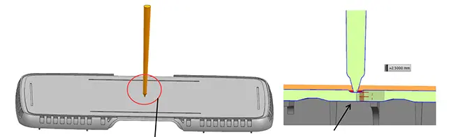
For example, with the long housing shown above, gating from one end requires the melt to travel a relatively long distance before reaching the opposite end, where air is more likely to accumulate. Moving the gate toward the center allows the melt to fill toward both ends simultaneously, shortening the flow length and shifting the last-to-fill areas to the two ends of the housing. Effective vents can then be placed at both ends to reduce the risk of burn marks caused by trapped air.
4) Maintain Balanced Filling
The goal of balanced filling is to ensure that different cavities or different areas of the part finish filling at roughly the same time, preventing one location from consistently becoming the last-to-fill region.
For example, in a multi-cavity mold, if one cavity has a longer runner or a smaller gate, it will fill later than the others, making it more likely for air to be compressed at the end of fill. Adjusting runner length and cross-section, as well as gate size and location, can bring the filling resistance of each cavity closer together and reduce localized air traps and burn marks.
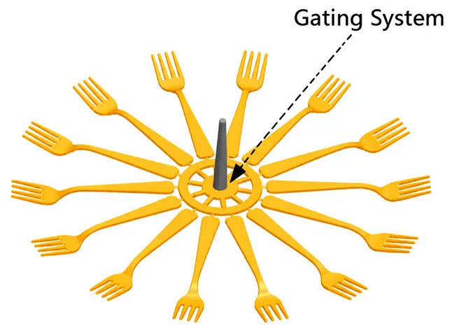
5) Use Mold Flow Analysis to Predict Air Traps
For complex parts, mold flow analysis can be used to predict melt flow paths, last-to-fill locations, and potential air traps before tooling is built.
Identifying these issues during the design stage makes it possible to optimize gate locations, venting, and part geometry in advance, reducing the need for repeated mold modifications later.
FAQ
Q1: Can burn marks affect the strength of plastic parts?
Minor burn marks may mainly affect appearance. However, if significant thermal degradation has occurred, the affected material may become brittle and its mechanical properties can decrease.
Q2: Why do burn marks often appear at the end of fill?
The end of fill is usually where the remaining air accumulates. If venting is insufficient, the trapped air is rapidly compressed and heated, which can scorch the plastic.
Q3: Can reducing injection speed eliminate burn marks?
It can improve some burn marks caused by trapped air, especially when the end-stage injection speed is reduced. However, if inadequate venting is the root cause, changing the speed alone usually will not eliminate the problem completely.
Q4: Why do burn marks appear in only one cavity?
This usually indicates a localized issue in that cavity, such as insufficient venting, a different gate condition, or unbalanced filling. The affected cavity should be inspected first.
Q5: Are burn marks always caused by excessive melt temperature?
No. Many burn marks are actually caused by trapped air and localized heating from rapid gas compression. The location of the burn mark should therefore be evaluated before simply lowering the melt temperature.