Flow marks, also known as flow lines or weld lines, are common defects that can occur in plastic molded parts. They appear as visible lines or streaks on the surface of the molded part and can negatively impact its aesthetics and mechanical properties. Several factors contribute to the formation of flow marks in plastic molds:

Mold Design: The design of the mold plays a critical role in preventing flow marks. Insufficient or improper gate placement can cause converging flow fronts, leading to flow marks. Gate size and shape should be optimized to ensure smooth and uniform filling of the mold cavity.

Material Selection: The choice of plastic material affects the flow behavior during molding. Materials with high melt viscosity are more prone to flow marks as they have difficulty flowing smoothly into the mold cavity.

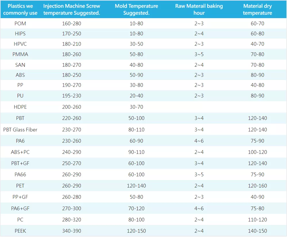
Melt Temperature: Improper melt temperature can result in inconsistent flow, leading to flow marks. The temperature should be set according to the material’s processing guidelines to ensure proper flow and packing.
Injection Speed and Pressure: Incorrect injection speed and pressure can cause abrupt changes in the flow pattern, resulting in flow marks. It’s essential to optimize these parameters to achieve uniform and controlled flow.
Wall Thickness: Variations in wall thickness across the part can lead to flow marks. Sharp changes in thickness cause differences in material flow and cooling rates, leading to visible lines.

Mold Temperature: Improper mold temperature can affect the cooling rate of the plastic and lead to flow marks. Maintaining a uniform and appropriate mold temperature is crucial to achieving consistent part quality.
Part Geometry: Complex part geometries with thin sections or intricate features can create challenges in achieving smooth flow and may result in flow marks.
Cooling Rate: Rapid cooling of the plastic material can contribute to flow marks. Proper cooling channels in the mold and controlled cooling rates are necessary to minimize this effect.
Injection Speed Transitions: Sudden changes in injection speed, such as fast-to-slow transitions, can cause flow marks at the transition point. Gradual transitions are preferred to minimize the impact.
Mold Venting: Inadequate mold venting can trap air or gas, leading to incomplete filling and flow marks on the surface of the part.
To prevent flow marks, it’s crucial to carefully consider all these factors during the design and molding process. Mold flow simulation software can also be used to predict potential flow marks and optimize the mold design and processing parameters accordingly. Regular maintenance and inspection of the mold can also help identify issues that may lead to flow marks and address them promptly.