


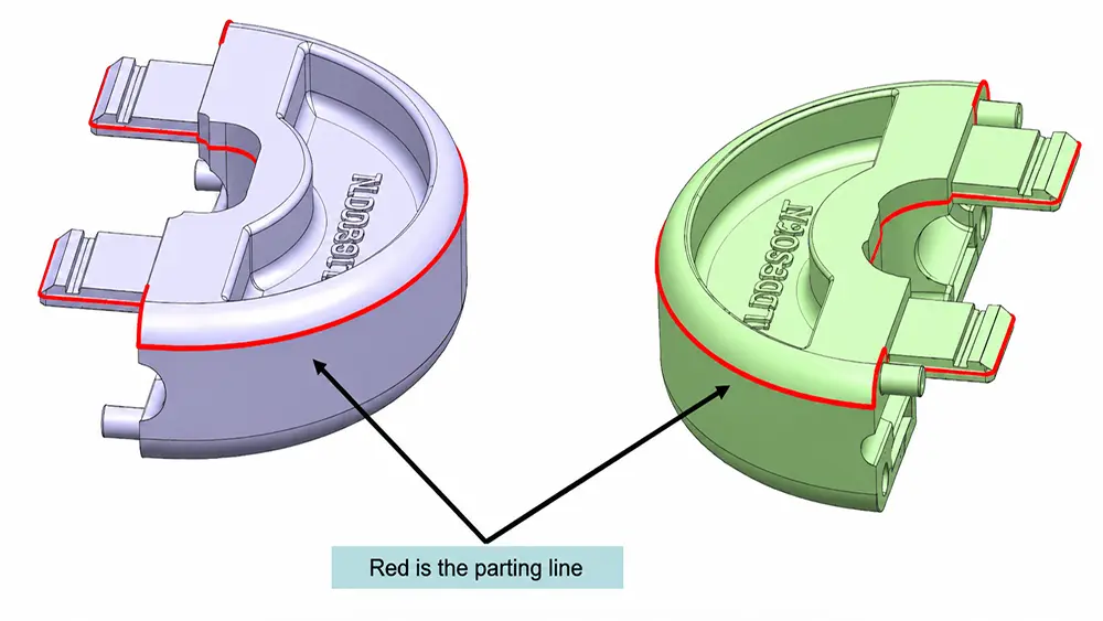
Choosing the wrong parting surface during mold design can cause far more trouble than simply leaving an extra line on the molded part. It may prevent the part from being released smoothly, require additional slides and increase mold costs, or even affect sealing performance, dimensional accuracy, and product appearance.
This article introduces the common types of parting surfaces, explains the main design principles, and uses three product examples to show how different parting solutions can affect the final result.
Note: In the injection molding industry, the terms “parting line” and “parting surface” are often used interchangeably. This article mainly discusses the design of mold parting surfaces, but the two terms may be used interchangeably depending on the context.
1. Types of Parting Surfaces
Common parting surface types used in injection molds include:
- Flat parting surfaces
- Stepped parting surfaces
- Inclined parting surfaces
- Curved parting surfaces
- Parting surfaces for tubular parts
- Shut-off parting surfaces for holes
These types are mainly classified according to the contour of the plastic part and the shape of the contact area between the core and cavity halves. In actual mold design, one mold may contain two or more types of parting surfaces.
Flat Parting Surface
A flat parting surface is a plane perpendicular to the mold-opening direction. This structure is simple, making machining, assembly, and maintenance relatively easy. It also provides stable shut-off conditions, so it should generally be considered first.
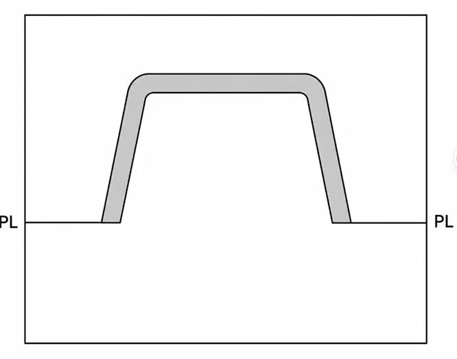

Design considerations:
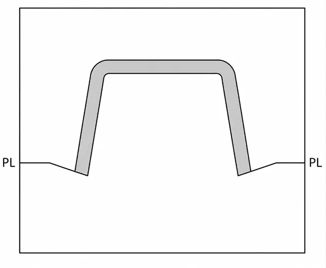
If the end face of the product is not perpendicular to the mold-opening direction, the surface can be extended to form a shut-off land, and the extended plane can then be used as the parting surface, as shown below.

Stepped Parting Surface
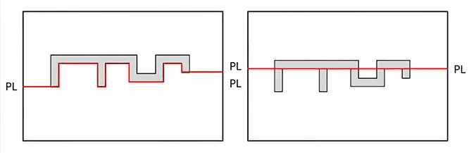
When different areas of a plastic part have obvious height differences and cannot be divided by a single flat surface, a stepped parting surface may be used.
Design considerations:
For a stepped parting line, some plastic parts are subjected to a greater force on one side of the cavity. This creates an off-center injection force between the stationary and moving mold halves, giving them a tendency to slide relative to each other.
In this situation, the preferred parting surface is the one with the shallower step and the larger projected area perpendicular to the mold-opening direction, as shown below.


If the step on the part is relatively high, a shut-off land can be added so that a flat plane can be used as the parting surface.
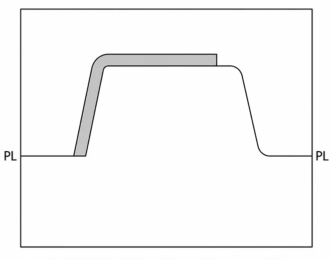

Some parts contain several stepped areas. If the parting surface follows every step, it may become unnecessarily complicated. To simplify the structure, the parting surface can instead be designed as a flat plane. The disadvantage is that a visible parting line will appear on the cosmetic surface, so this approach is more commonly used for internal components.

Inclined Parting Surface
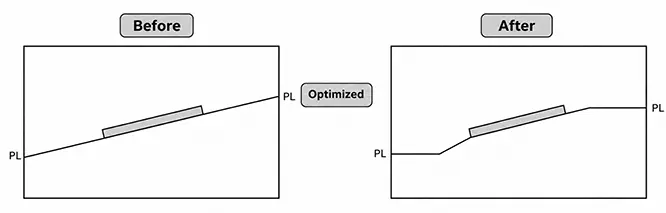
Inclined parting surfaces are commonly used along product edges, sloped sidewalls, or special cosmetic contours. The parting area forms a certain angle with the mold-opening direction.
Design considerations:
When designing an inclined surface, make sure the two mold halves can separate normally and that sufficient shut-off width is provided. This helps reduce mold wear and flash while also making the mold easier to machine.

Curved Parting Surface
A curved parting surface follows the curved or irregular contour of the plastic part. It is commonly used for products with complex cosmetic surfaces.
Design considerations:
Similar to an inclined parting surface, a short shut-off surface can first be created along the curved product contour. The outer parting area can then be flattened to make mold fitting and polishing easier.
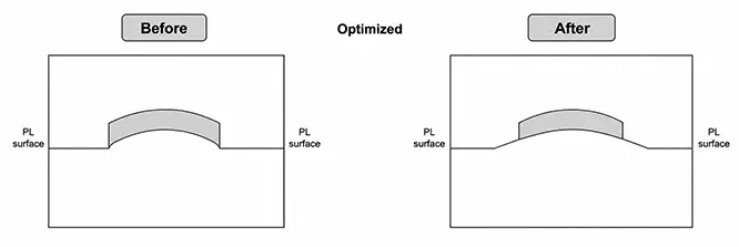

However, the strength of the mold steel must be considered when extending the surface. Thin, sharp, or structurally weak steel sections should be avoided.
Parting Surfaces for Tubular Parts
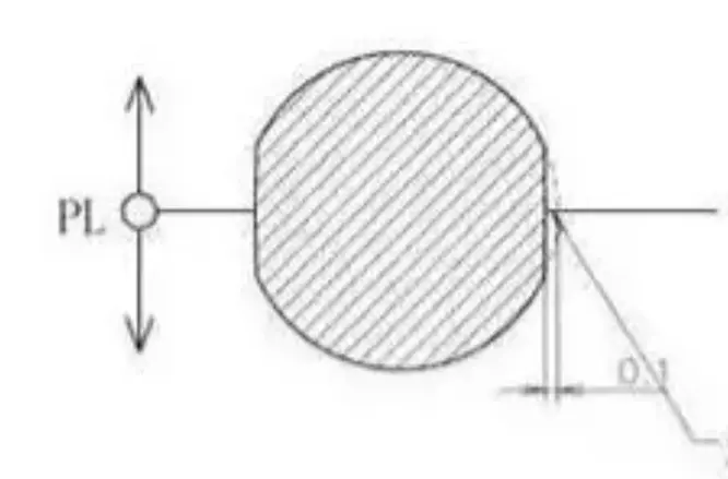
Tubular, cylindrical, or ring-shaped plastic parts are usually divided along their axial contour or at their maximum diameter.
Design considerations:
The parting line is normally positioned at the maximum diameter. When necessary, a slight recess or a small flat land may be added at the parting position. This makes mold fitting easier and reduces the effect of mismatch and flash on the outer cylindrical surface.

Shut-Off Parting Surfaces for Holes
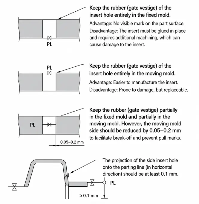
For side holes, through-holes, or local openings, the hole can be formed by allowing the core and cavity inserts to shut off directly against each other. This may eliminate the need for an additional slide.

2. Parting Surface Design Principles
There is no single parting surface solution that works for every product. In most cases, the design should be evaluated step by step, with priority given to demolding feasibility, product quality, and mold complexity.
Meet the Demolding Requirements
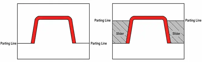
The selected parting surface must allow the part to be released from the mold.
As a basic principle, the main parting surface should be located at the maximum projected contour of the part in the demolding direction. Following this principle usually simplifies the mold structure. Otherwise, additional mechanisms, such as slides, may be required, making the mold more complicated.

Help the Plastic Part Release Smoothly
Meeting the mold-opening requirements does not necessarily mean that the plastic part will be released reliably.
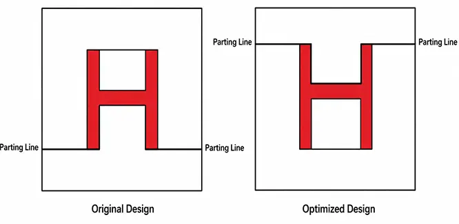
Because the ejection system of an injection molding machine is located on the moving mold side, the parting surface should, whenever possible, be designed so that the molded part remains on the moving half after the mold opens. This allows the ejector system installed on the moving side to operate normally.
Adding an ejection mechanism to the stationary mold half would increase the complexity of the mold.

Maintain Dimensional Accuracy and Surface Quality
Parts with strict coaxiality requirements:
When selecting the parting surface, features that require high coaxiality should ideally be formed on the same side of the mold, as shown below.
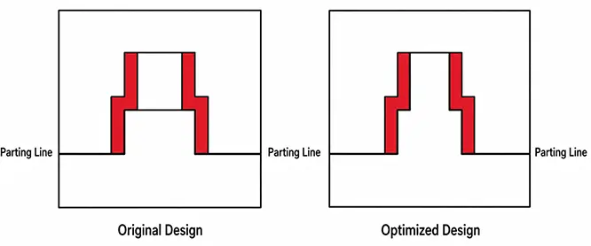

The stepped hole in the center requires high coaxial accuracy. In the original parting design, the stepped hole is formed by two separate cores located on the stationary and moving mold halves. After the mold closes, it is difficult to maintain precise coaxial alignment between the two cores.
In the optimized design, the entire stepped hole is formed by a single core, making its dimensional and coaxial accuracy much easier to control during machining.
Plastic parts with cosmetic surface requirements:
The position of the parting surface should also take into account how the resulting parting line will affect the appearance of the product.
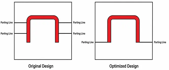

Make the Mold Easier to Machine
Simple and continuous parting surfaces are easier to manufacture by CNC machining, EDM, grinding, and mold fitting.
Provided that the product requirements can still be met, flat or relatively simple parting contours should be preferred. Unnecessary bends, sharp corners, and narrow shut-off areas should be avoided.
For example, if several shut-off lands are located on the same side, they may be combined into one larger shut-off area, with the individual features formed by the core. This simplifies the parting surface and makes the mold easier to machine.
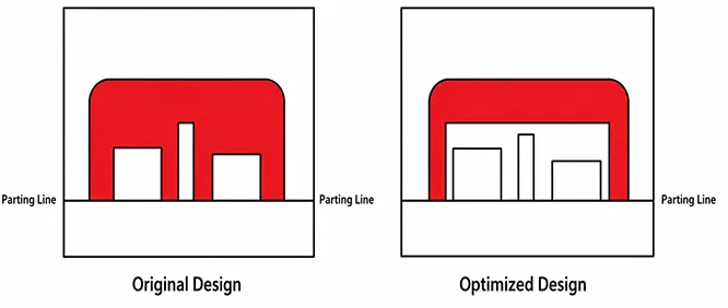

Improve Mold Venting
Air inside the cavity is normally pushed toward the end of the filling path and the parting surface by the molten plastic. A properly positioned parting surface can therefore help the mold vent more effectively.
In general, the parting surface should be positioned as close as possible to the end of the plastic flow path to facilitate air release.
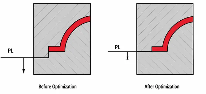

Simplify the Mold Structure
If side features do not have strict dimensional requirements, side-action core-pulling mechanisms, such as slides, should be avoided whenever possible.
Simplifying the mold structure can reduce the overall mold size and, to some extent, lower the mold cost.
When a slide mechanism cannot be avoided, the parting surface should be selected to minimize the side core-pulling distance, which helps keep the mold more compact.
Large cores should also be aligned with the mold-opening direction. Because the plastic part may grip tightly around a large core as it shrinks, placing such a core in a side-action mechanism can make demolding more difficult.
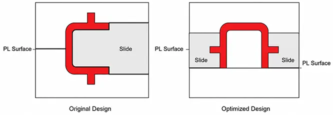

Need Help Determining the Right Parting Solution?
At RJC Mold, we can provide a DFM analysis before mold development begins. We evaluate the parting surface location, demolding direction, undercuts, slides, thin steel sections, shut-off conditions, sealing requirements, and cosmetic risks, and then provide practical optimization recommendations.
Mold design, manufacturing, mold trials, and volume injection molding can all be completed in-house. Send us your 3D drawings and project requirements to discuss a more suitable parting solution.
3. Parting Surface Design Examples
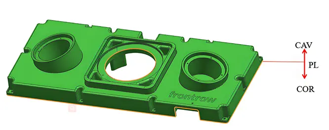
Example 1: Plastic Housing with an O-Ring Groove — Protecting the Sealing Area
As shown in the illustration, an O-ring groove is located around the middle of the part. The parting line is positioned along the inner edge of the groove rather than across the primary sealing contact surface.
This arrangement meets the mold-parting requirements while reducing the risk that flash or mold mismatch will affect the sealing performance.

Example 2: Electronic Housing with Snap-Fit Features — Controlling Mold Structure and Cost
Snap-fit features on electronic housings can easily create undercuts, so the placement of the parting surface is particularly important.
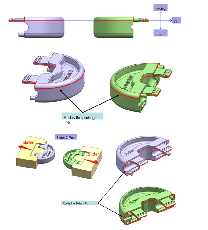

Features such as snap-fits and side holes directly affect how the parting surface should be arranged. As shown in the illustration, the parting surface passes through the snap-fit and side features, allowing them to be formed by the core and cavity halves or by slides.
For this type of product, a better-designed parting surface usually results in a simpler mold structure. It can also reduce machining, assembly, and long-term maintenance costs.
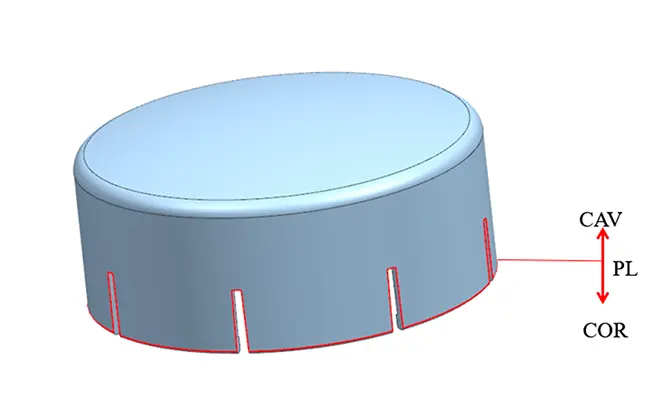
Example 3: Cosmetic Packaging — Controlling the Visible Parting Line
Products such as cosmetic caps and compact cases usually have strict appearance requirements. Their parting lines are therefore commonly positioned along the bottom edge, a side corner, or another less noticeable location.
This prevents the parting line from affecting the front cosmetic surface and helps preserve the overall appearance and perceived quality of the product.

FAQ
Q1: Must the parting surface always be located at the maximum contour of the plastic part?
No. Positioning it at the maximum contour often makes demolding easier, but appearance, undercuts, dimensional accuracy, the side on which the part should remain after opening, and the overall mold structure must also be considered.
Q2: Can one plastic part have multiple parting surfaces?
Yes. In addition to the main parting surface, a complex product may have secondary parting surfaces around slides, lifters, inserts, and shut-off structures.
Q3: Can the parting line on a molded product be completely eliminated?
Usually not. However, its visibility can be reduced by adjusting its position, improving mold machining and fitting accuracy, and optimizing the molding parameters.
Q4: Is a complex parting surface always better than a flat one?
No. A complex parting surface may improve appearance or accommodate special product features, but it also makes mold machining, fitting, maintenance, and flash control more difficult.
When a simple parting surface can meet the product requirements, there is usually no reason to make it unnecessarily complicated.