Snap-fits can reduce the need for screws, adhesives, and additional assembly operations, but a reliable snap-fit is more than simply adding a hook. The design must consider the material’s allowable strain, snap-fit deflection, beam dimensions, mating tolerances, as well as injection molding and tooling requirements. This article focuses on how to design snap-fits for injection molded parts based on product requirements.
1. Common Types of Snap-Fits
1) Cantilever Snap Fit
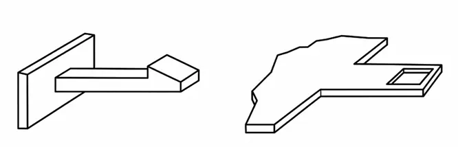
A cantilever snap fit uses beam bending to achieve assembly and retention. It is the most common type used in injection molded plastic parts and is widely used in housings, covers, panels, and similar structures.
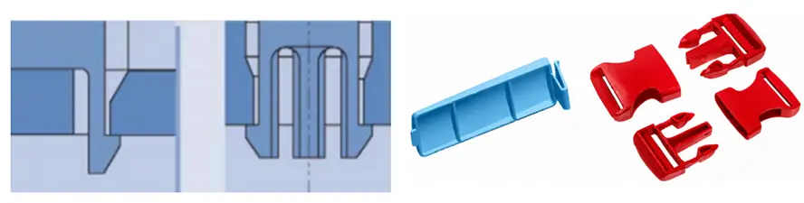
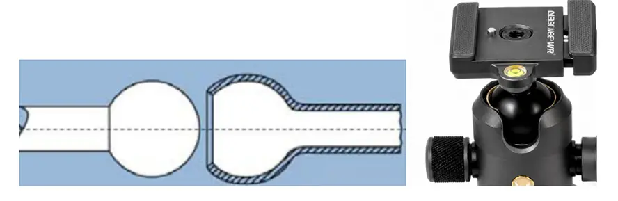
2) Annular Snap Fit
An annular snap fit relies on radial expansion or contraction around the circumference to achieve engagement. It is commonly used for cylindrical, ring-shaped, or ball-and-socket type connections. Split annular snap-fits are also included in this category.
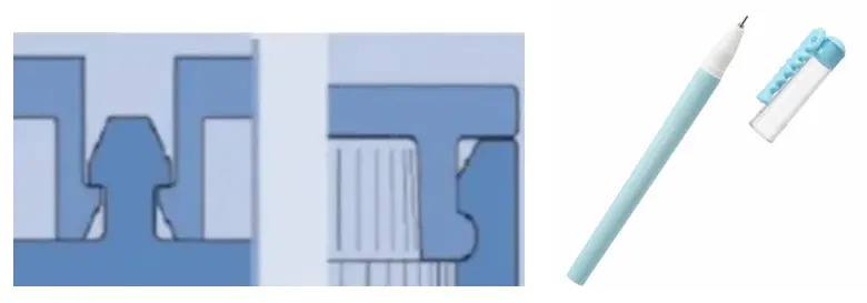
3) Torsional Snap Fit
A torsional snap fit primarily relies on torsional deformation for locking or release and is commonly used in structures that require push-to-release or repeated opening.
In addition, U-shaped, L-shaped, and split-type snap-fits can generally be considered variations of the three basic types above.
When selecting a snap-fit type, consider the product structure, assembly direction, available space, whether disassembly is required, and the expected number of assembly cycles. The following sections focus on the most common type: the cantilever snap fit.
2. Key Snap-Fit Design Dimensions
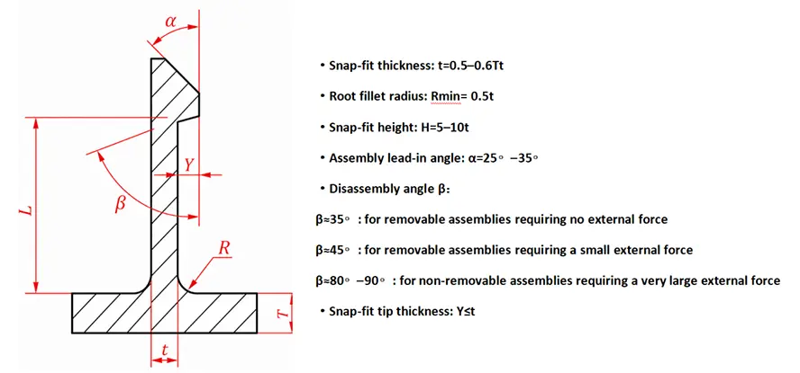
The dimensions of a cantilever snap fit are interrelated. During the initial design, the beam thickness can first be determined based on the main wall thickness and snap-fit layout. The beam length can then be determined based on the engagement depth, allowable material strain, and available space, followed by adjustment of the beam width, root radius, and hook angles.
1) Snap-Fit Beam Root Thickness (t)
The beam thickness can initially be referenced to the main wall thickness T. For a cantilever snap fit extending directly from the main wall, the beam root thickness t can initially be set to: t = 0.5T–0.6T
If the snap-fit beam is a direct extension of the main wall, its root thickness can be close to the main wall thickness: t ≈ T
This ratio is only an initial reference. A beam that is too thick will increase stiffness, assembly force, and bending strain. The final design still needs to be checked against the beam length, deflection, and allowable material strain.
2) Retention Face Depth
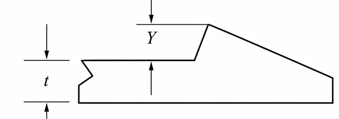
The retention face depth Y affects the degree of deflection during engagement and disengagement, as well as the retention force. It can be initially determined based on the ratio of effective beam length L to beam thickness t:
When L / t ≈ 5: Y < t
When L / t ≈ 10: Y ≈ t
For materials with higher stiffness or lower allowable strain, Y should be reduced accordingly. The final design should be verified through strain calculations to ensure that the maximum strain at the beam root does not exceed the allowable strain of the material.
3) Snap-Fit Beam Length (L)
Beam length L is the effective cantilever length measured from the fixed root to the retention feature.
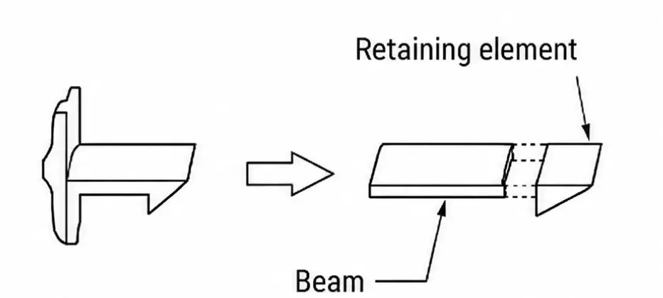
As an initial design reference: L ≥ 5t
Where space permits, it can be increased to approximately: L ≈ 10t
When L is less than 5t, the beam has relatively low flexibility and the beam root is subjected to greater bending, increasing the risk of damage. When L exceeds 10t, problems such as warpage and incomplete filling may occur.
4) Snap-Fit Beam Width
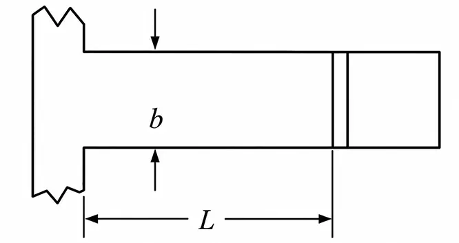
The beam width b is mainly used to adjust assembly force and retention force. A wider beam generally increases assembly force, disengagement force, and retention strength, while a narrower beam is easier to deflect.
A conventional cantilever snap-fit generally uses an approximately constant beam width, with: b ≤ L / 2
5) Tapered Beam Design
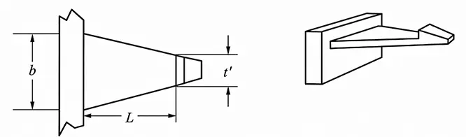
If the strain at the beam root needs to be reduced, the beam width can also be gradually reduced from the root toward the end, but the effect is less significant than tapering the beam thickness. Generally, a width taper of approximately 4:1 (L/b) is required to achieve a strain reduction effect comparable to a thickness taper of approximately 2:1 (L/t).
6) Root Fillet
As with other structures, the snap-fit root is a typical stress concentration area, so sharp corners should be avoided. The fillet radius R can initially be considered at approximately 50% of the beam thickness: R ≈ 0.5t
A radius that is too small can result in excessive stress concentration, while an excessively large radius may create a locally thick section. The design therefore needs to balance strength with uniform wall thickness for injection molding.
7) Lead-In Angle (α) and Retention Angle (β)
The lead-in angle mainly affects assembly force. The shallower the angle, the more easily the snap-fit can pass over the mating feature. For a typical cantilever snap fit, the lead-in angle α can initially be designed at 20°–30°. If a shorter lead-in distance is required, 30°–45° can also be used, although the assembly force will generally increase.
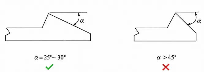
The retention angle β mainly determines how easily the snap-fit can be disengaged:
Disassemblable snap-fit: 30°–45° can be used as a common starting point
Higher retention force: 45°–60°
Permanent snap-fit: close to 90°, forming an approximately vertical locking face
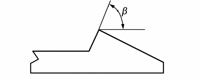
In simple terms:
Smaller lead-in angle → easier assembly
Larger retention angle → more difficult disassembly
However, the final angles should also be evaluated based on the material’s coefficient of friction, snap-fit stiffness, engagement depth, and actual assembly force. The angle alone should not be used to determine performance.
3.Injection Molding Design for Snap-Fit Manufacturability
A snap-fit that functions properly as a product structure is not necessarily easy to manufacture by injection molding. Hooks, undercuts, the parting direction, and wall thickness at the beam root can all directly affect the mold design.
1) Undercuts and Mold Opening Direction
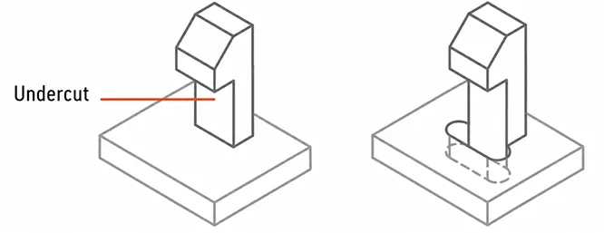
The retention feature of a snap-fit can easily create an undercut. If the undercut conflicts with the mold opening direction, a side-action mechanism such as a slider or lifter is usually required, increasing mold complexity and cost.
During product design, first consider whether the undercut can be eliminated by adding an opening, changing the snap-fit direction, or adjusting the parting line. For example, adding a through-hole beneath the snap-fit root may allow the core to form the retention face directly, potentially eliminating the need for side action.
2) Provide Clearance for Lifter Retraction
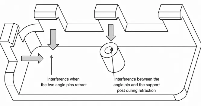
If the snap-fit undercut must be released using a lifter, sufficient clearance should be provided according to the lifter’s direction of movement to prevent interference with adjacent snap-fits, bosses, ribs, or other structures.
At the same time, the top of the lifter should not encounter a reverse draft that prevents it from retracting smoothly.
3) Provide an Appropriate Draft Angle
Non-functional side walls of the snap-fit beam and retention feature that are parallel to the demolding direction should have an appropriate draft angle. For smooth surfaces, 0.5°–1° is generally sufficient; where conditions allow, 1°–2° provides easier demolding.
The angle of the retention face is primarily determined by the locking function of the snap-fit and should not be changed arbitrarily just to improve draft.
4) Avoid Thick Sections at the Root
The connection between the snap-fit and the main body can easily create a locally thick section, resulting in sink marks, uneven cooling, or warpage.
The wall thickness should therefore be kept as uniform as practical. Avoid excessive material buildup at the snap-fit root and use appropriate fillets and gradual transitions to form the connection.
5) Avoid Weld Lines at the Snap-Fit Root
The snap-fit root is typically a high-stress area, so weld lines should be avoided there whenever possible. In particular, the snap-fit should not be positioned where the melt is likely to split and then recombine after passing around holes, large openings, or complex rib structures.
If a weld line cannot be avoided, the gate location and melt flow direction should be reviewed during the DFM stage so that the weld line is positioned away from the snap-fit root as much as possible.
4. Snap-Fit Deflection, Strain, and Material Selection
During assembly, a snap-fit must undergo elastic deformation so that the hook can pass over the mating feature and then recover to achieve locking. The required deformation should be kept within the allowable strain range of the material, particularly at the snap-fit root.
Deflection
The required snap-fit deflection is generally related to the undercut depth. A larger undercut requires greater beam deflection, which also increases root strain and assembly force. Therefore, the undercut should not be made larger than necessary to achieve the required retention force.
Maximum Strain
For a cantilever snap fit, the maximum strain typically occurs at the beam root and can be estimated using: ε = 1.5tY/L²Q
Q is the deflection amplification factor, which is determined by the snap-fit structure and the L/t ratio. The calculated maximum strain should be lower than the allowable strain of the material.
Material Selection
The snap-fit material needs sufficient allowable strain and toughness. PP, POM, and PA are common snap-fit materials; ABS and PC can also be used for structures with relatively small deflections.
For snap-fits that require repeated assembly and disassembly, fatigue performance and long-term creep should also be considered.
5. Common Snap-Fit Failures and Optimization Methods
| Problem | Common Causes | Optimization Methods |
| Snap-fit breaks during assembly | Beam too short or too thick, excessive engagement depth, stress concentration at the root, or insufficient allowable strain of the material | Increase the effective beam length, reduce thickness appropriately, reduce engagement depth, increase the root fillet, and recalculate the strain |
| Whitening after assembly | Excessive local strain; material is approaching or exceeding its elastic deformation range | Reduce the required deflection, optimize beam length and thickness, and check the root fillet |
| Excessive assembly force | Beam stiffness too high, lead-in angle too steep, excessive engagement depth, or excessive friction | Optimize the lead-in angle, reduce beam stiffness, and reduce engagement depth |
| Snap-fit is too loose or easily disengages | Insufficient engagement, retention angle too small, dimensional variation, shrinkage, or warpage | Adjust engagement depth and retention angle while checking actual injection molded dimensions and tolerances |
| Retention force decreases after a period of use | Creep or stress relaxation caused by long-term loading | Reduce the continuous deformation of the snap-fit and select a material with more suitable creep resistance |
| Prototype works normally but fails in mass production | Prototype material differs from production material, or actual molded parts have shrinkage, warpage, weld lines, or dimensional variation | Re-validate assembly force, retention force, and dimensions using production material and actual injection molded parts |
6. Case Study — Manufacturability Design of a Cantilever Snap-Fit for a Plastic Housing
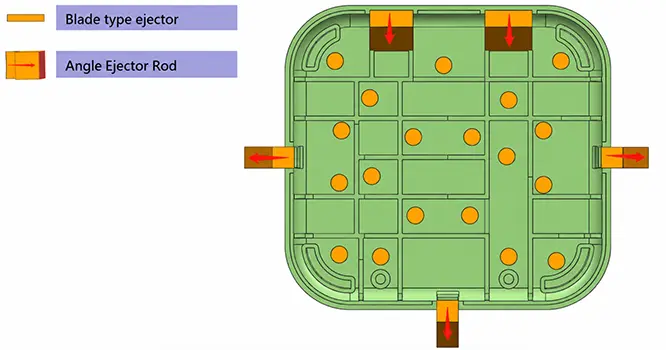
As shown below, the product has three cantilever snap-fits along the edge of the housing for positioning and locking with the mating part.
The product contains numerous internal ribs and bosses, so the undercuts of the snap-fits are designed to face outward from the housing. This allows the lifters to retract outward, avoiding interference with the internal ribs and bosses. It also eliminates the need to significantly modify the internal structure to accommodate lifter movement.
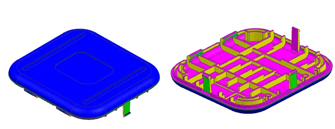
Because the retention faces create lateral undercuts, the three snap-fits are released using lifters. This arrangement satisfies the assembly and retention requirements while also providing a clear path for demolding, demonstrating how snap-fit design can address both product functionality and injection molding manufacturability at the product design stage.
FAQ
Q1: Why do tolerances affect snap-fit performance?
Because the actual engagement is determined by the final dimensions of both mating parts. Tolerance stack-up can make the snap-fit too loose or increase deflection and assembly force, so the nominal CAD dimensions alone are not enough.
Q2: Is a thicker snap-fit always stronger?
No. Increasing the thickness significantly increases beam stiffness while also increasing root strain and assembly force. If a snap-fit is breaking, simply making it thicker can actually make the problem worse.
Q3: Does a snap-fit always require a slider or lifter?
Not necessarily. If the undercut can be eliminated through a through-hole, shutoff, adjustment of the parting line, or a change in snap-fit direction, a slider or lifter can be avoided.
Q4: Which plastic is best for snap-fits?
There is no single material that is suitable for every snap-fit. PP, PA, POM, ABS, and PC can all be used, but the specific grade should be selected based on allowable strain, stiffness, number of assembly cycles, temperature, and long-term loading.
Q5: If a snap-fit works in a 3D-printed prototype, can the mold be released directly?
Not recommended. 3D-printing materials, interlayer strength, and dimensional accuracy differ from those of the final injection molded part. 3D printing can be used to verify the structure and assembly concept, but final performance should still be confirmed using the actual injection molding material and trial-molded parts.