Bosses are very common structural features in injection molded parts. They are mainly used for screw fastening, threaded insert installation, part positioning, and support. Although a boss may look simple, improper wall thickness, dimensions, or reinforcement can easily lead to sink marks, cracking, deformation, or screw fastening failure. This guide covers the key dimensions, design principles, screw and insert applications, and other important considerations for boss design in injection molded parts.
1. Key Boss Dimensions
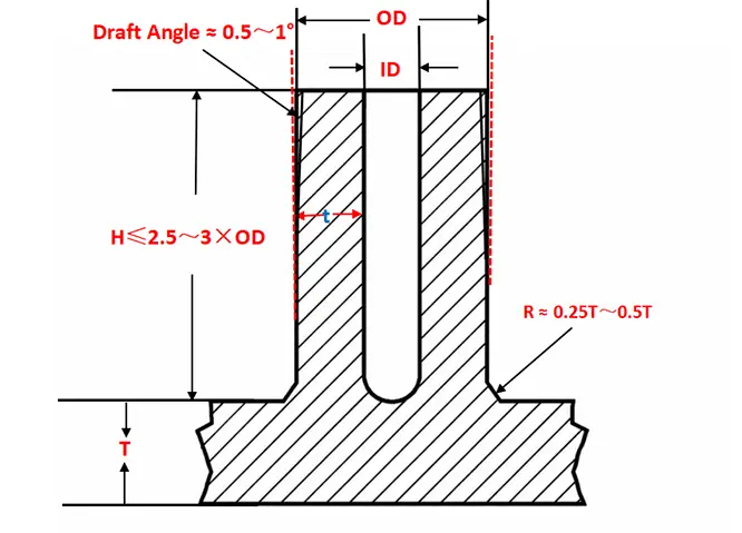
Boss dimensions directly affect structural strength, assembly performance, and molding quality. The following values can be used as initial design references, but the final dimensions should still be adjusted based on the material, screw specification, and mold structure.
1) Boss Wall Thickness
A commonly recommended boss wall thickness is:
Boss wall thickness ≈ 0.4T–0.6T (T = nominal part wall thickness)
If the boss wall is too thick, the risk of sink marks, voids, and uneven cooling increases. If it is too thin, the boss may not provide sufficient strength. When additional strength is required, adding ribs is generally preferable to simply increasing the boss wall thickness.
2) Boss Height
Bosses should not be designed excessively tall. A commonly used guideline is:
Boss height H ≤ 2.5–3 × OD
For example, if the boss outside diameter is 6 mm, the height should preferably be kept within approximately 15–18 mm.
An excessively tall boss has lower lateral stability and may increase the risk of core pin deflection while also making ejection and cooling more difficult to control. If a taller boss is unavoidable, ribs should be added or the boss should be connected to a nearby side wall.
3) Boss Outside and Inside Diameters
The outside diameter and inside diameter together determine the boss wall thickness:
Boss wall thickness = (OD − ID) ÷ 2
For screw fastening applications, the boss outside diameter can initially be designed at approximately 2 times the nominal screw diameter.
For example:
M3 screw → Boss OD ≈ 6 mm
The inside diameter, or Pilot Hole, should not be determined using one universal ratio. It depends on the screw type and plastic material. For some screws specifically designed for plastics, the recommended pilot hole diameter is approximately 0.8–0.85 times the screw diameter, but supplier recommendations should take priority in the final design.
4) Boss Base Radius and Thickness
A fillet should be added at the base of the boss to reduce stress concentration. A common reference is:
Base radius R ≈ 0.25T–0.5T
If the radius is too small, stress concentration becomes more severe. If it is too large, excessive material can accumulate around the boss base and increase the risk of sink marks. The design should therefore balance structural strength with uniform wall thickness.
5) Boss Draft Angle
Both the inside and outside walls of a boss require sufficient draft. For a typical smooth boss surface, a useful initial reference is:
Approximately 0.5°–1° per side
For taller or deeper bosses, the draft may need to increase to approximately 1°–2°. Lightly textured surfaces may require around 3°, while heavy textures may require 5° or more.
The taller the boss, the greater the dimensional difference between the top and bottom caused by draft. Therefore, when Pilot Hole dimensions are critical, both the hole opening and the bottom diameter should be checked.
2. Boss Design Principles
1) Maintain Uniform Wall Thickness
Boss design should first avoid excessive local material thickness.
If a boss is directly connected to the outer wall of a part and the connection is significantly thicker than the nominal wall, sink marks can easily appear on the cosmetic surface.
Material transitions should be kept as gradual as possible, and large solid sections at the base of the boss should be avoided.
When more boss strength is needed, ribs should be considered before simply increasing wall thickness.
2) Connect the Boss to Part Walls Properly
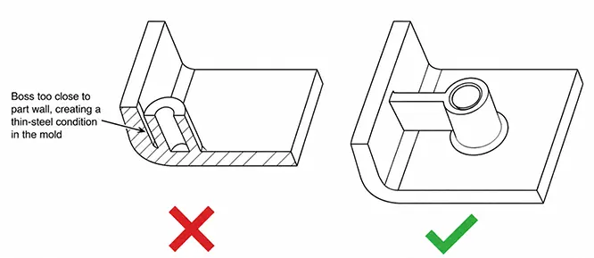
A boss should not be positioned too close to a side wall. If the gap is too small, it can create a large locally thick section between the boss and wall, resulting in sink marks and uneven cooling. At the same time, the corresponding mold steel may become too thin, increasing machining difficulty and weakening the mold locally.
If the side wall needs to support the boss, leave a reasonable gap and connect the boss to the wall using a relatively thin rib.
3) Add Reinforcement Ribs Around an Isolated Boss
When a boss is located far from a side wall, is relatively tall, or needs to withstand significant lateral loads, reinforcement ribs or gussets can be added around it.
These ribs improve the lateral stiffness of the boss and distribute screw installation loads over a larger area.
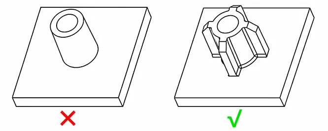
The ribs themselves should not be made excessively thick. Otherwise, strengthening the boss may introduce a new sink-mark problem.
A more appropriate boss reinforcement strategy is:
Proper boss wall thickness + suitable reinforcement ribs
3. Boss Design for Screw Fastening
1) Self-Tapping Screw Boss
When designing a boss for a self-tapping screw, first determine the screw size, thread form, and length. Then use the screw diameter to establish the Pilot Hole, boss outside diameter, thread engagement length, and other key dimensions. Among these, the Pilot Hole is one of the most important factors affecting fastening strength and boss cracking.
For general thermoplastics, the single-side thread engagement depth (E) can initially be estimated at approximately 10% of the nominal screw diameter D: E ≈ 0.1D
The corresponding Pilot Hole diameter can be estimated as: Pilot Hole ≈ D − 2E
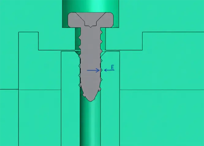
Take an M1.4 self-tapping screw as an example. The maximum screw outside diameter is 1.4 mm, the minimum core diameter is approximately 1.05 mm, and the minimum threaded length is 2.5 mm, excluding the screw head. Based on the method above, the single-side thread engagement depth E can be approximately 0.14–0.15 mm, corresponding to a Pilot Hole diameter of approximately 1.10–1.12 mm.
2) Pilot Hole Design
The Pilot Hole should be determined based on:
Screw type + Plastic material + Boss dimensions
If the Pilot Hole is too small, the screw creates excessive radial pressure in the surrounding plastic during installation, which may cause the boss to crack.
If the Pilot Hole is too large, thread engagement with the plastic becomes insufficient, increasing the risk of thread stripping or screw pull-out.
3) Boss Cracking and Hoop Stress
When a screw is driven into a boss, it generates outward hoop stress in the boss wall.
The following conditions increase the risk of cracking:
- Boss wall is too thin;
- Pilot Hole is too small;
- The material is relatively brittle;
- The boss base radius is insufficient;
- Assembly torque is too high.
Boss dimensions, Pilot Hole size, and screw installation conditions should therefore be controlled together.
4. Boss Design for Threaded Inserts
1) Heat-Set and Ultrasonic Brass Inserts
For heat-set or ultrasonic brass inserts, the key boss design considerations are the hole diameter, boss outside diameter, and top and bottom clearances. The goal is to allow the brass insert to be installed smoothly while avoiding boss cracking or sink marks on the cosmetic surface.
Common design references are as follows:
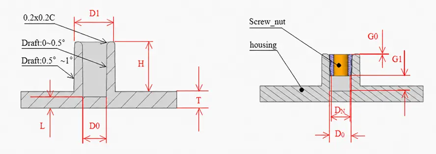
Boss hole diameter D0 = DN + 0.05 mm
(where DN is the guide diameter at the lower end of the brass insert)
Boss outside diameter D1 = D0 + 2 × 0.6T
(where 0.6T is the minimum boss wall thickness reference; in practice, approximately 0.85–0.9 mm is commonly used to reduce the risk of boss splitting during heat installation)
Top clearance G0: 0.05–0.1 mm
Bottom clearance G1: ≥ 0.5 mm: Adjust according to the available structural space.
Bottom wall thickness L: approximately 0.6–0.8T: Provide sufficient structural strength while avoiding sink marks on the opposite surface.
Boss height H: approximately 2T–5T: Determine according to the brass insert length and available product space.
Other design considerations include:
A chamfer of approximately 0.2 × 0.2 mm can be added at the boss hole entrance to help locate and guide the brass insert during installation;
The draft angle of the boss hole should not be excessive. Approximately 0.5° can be used as an initial reference to avoid affecting insert retention;
The boss outside wall can typically use a draft angle of approximately 1°.
These dimensions can be used as initial design references. Final values should still be adjusted according to the brass insert specification, plastic material, and supplier recommendations.
2) Molded-In Inserts
For a molded-in insert boss, the main design considerations are plastic encapsulation thickness, bottom thickness, base radius, and insert position. Sufficient plastic should surround the insert to prevent cracking. The bottom section should not be excessively thick, as this can increase sink-mark risk. A fillet should be added at the boss base, and the insert should not be positioned too close to an outer wall or other weak section of the part.
5. Case Study — Preventing Sink Marks in a Screw Boss
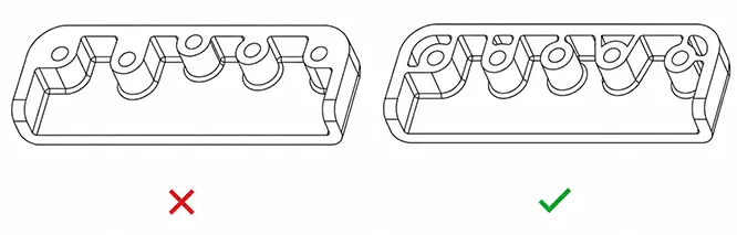
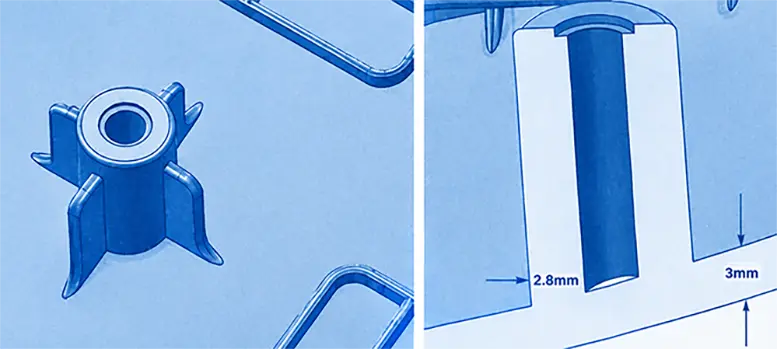
As shown below, this screw boss must maintain an outside diameter of 9 mm to provide sufficient resistance to cracking during screw installation. The screw hole inside diameter is 3.4 mm, resulting in a single-side boss wall thickness of approximately 2.8 mm. This creates a significantly thick section at the base of the boss, making sink marks likely to appear on the opposite surface of the part.
When the boss outside diameter cannot be reduced, the conventional cylindrical boss can be redesigned as a tower-shaped structure. As shown in Figure 5, the upper section of the boss retains the required outside diameter, inside diameter, and height to maintain screw fastening strength. The lower section eliminates the large thick-wall connection and instead uses support ribs approximately 1 mm thick to connect the boss to the main body.
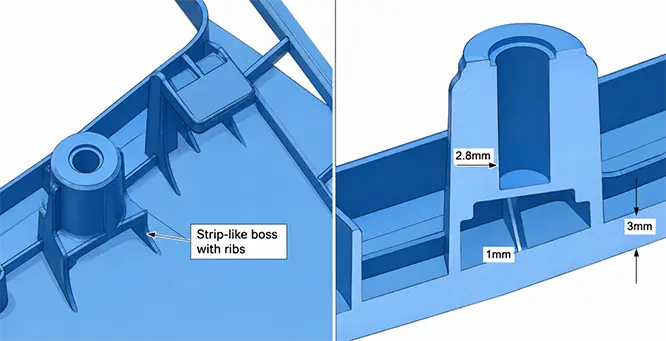
This structure preserves the functional dimensions required for the screw boss while reducing material accumulation around the boss base, thereby lowering the risk of sink marks on the opposite surface.
FAQ
Q1: Why not simply make the boss thicker to increase strength?
An excessively thick boss creates a locally thick section, which can cause sink marks, voids, and uneven cooling. When greater strength is required, ribs or connections to nearby walls are usually more effective.
Q2: Can a boss be placed directly behind a cosmetic surface?
Yes, but with caution. Material buildup at the boss base may cause visible sink marks, so the boss wall thickness and connection structure should be carefully controlled.
Q3: Why is a chamfer usually added at the top of a boss?
A suitable chamfer helps guide screws, inserts, or mating components into the boss hole and reduces the chance of misalignment during assembly.
Q4: Does every tall boss need reinforcement ribs?
Not necessarily. However, taller bosses generally have lower lateral stiffness. If the boss must withstand side loads or screw installation forces, reinforcement ribs are usually beneficial.
Q5: Is a DFM review still necessary after the boss dimensions have been finalized?
Yes. The final design should still be reviewed for material shrinkage, mold steel thickness, core strength, ejection, and cosmetic sink-mark risks to confirm that the part can be molded reliably.