
Plastic part design directly affects product performance, injection molding, mold construction, and production cost. Addressing key factors such as wall thickness, strength, draft, and assembly early in the design stage can reduce costly mold modifications and production risks later.
1. Wall Thickness Design
If the wall is too thin, molten plastic may have difficulty filling the cavity, which can lead to short shots, insufficient strength, and deformation. Excessive wall thickness, on the other hand, increases material usage and cooling time while raising the risk of sink marks and internal voids.
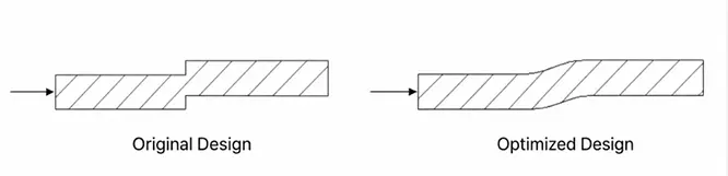
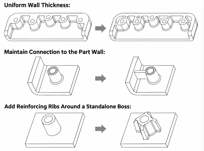
The wall thickness of a plastic part should be kept as uniform as possible. When different thicknesses are necessary, use gradual transitions rather than abrupt changes.

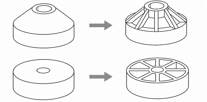
Overly thick local sections can be optimized by coring them out, using core features, or adding ribs.
For more details on wall thickness design, see: https://rjcmold.com/guides/wall-thickness-design/
2. Fillet and Sharp Corner Design
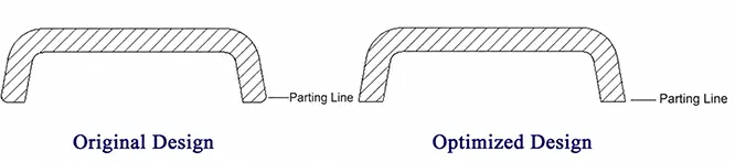
Unnecessary sharp corners should be avoided in plastic parts, especially at changes in the melt flow direction and where two features meet. Sharp internal corners not only restrict material flow but also create stress concentrations, making the part more likely to crack under load.
However, parting-line areas are an exception. At some mold parting edges, keeping a sharp 90-degree corner can provide a cleaner and more reliable shut-off surface.
For more details on fillet design, see: https://rjcmold.com/guides/fillet-design-guide/
3. Draft Angle Design
Surfaces parallel to the mold-opening direction generally require a draft angle so that the molded plastic does not grip the core too tightly as it cools and shrinks.
For ordinary smooth surfaces, 1°–2° is usually a practical starting point. Even when space is limited, some draft should be provided wherever possible.
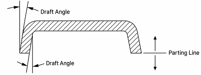
The required draft angle mainly depends on:
- Deeper parts generally require more draft;
- Materials with higher shrinkage may require more generous draft;
- Deeper surface textures require larger draft angles;
- Different ejection methods and part geometries also affect the required draft.
For more details on draft angles, see: https://rjcmold.com/guides/injection-molding-draft-angle/
4. Rib Design
Ribs increase part stiffness without requiring excessive wall thickness. Key dimensions to consider include rib thickness, height, spacing, root radius, and draft angle.
As a starting point, rib thickness is typically about 40%–60% of the nominal wall thickness, while rib height is generally limited to around 2.5–3 times the wall thickness. Ribs that are too thick can cause sink marks on the opposite surface, while excessively tall ribs may create filling and ejection problems. Also consider the following:
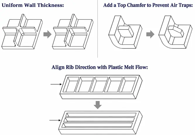
- Keep the rib root transition smooth to avoid creating excessively thick sections;
- Add a suitable chamfer at the rib tip to reduce the risk of trapped air;
- Where possible, orient ribs in the direction of plastic melt flow;
- When greater stiffness is required, several properly sized ribs are usually better than one overly thick and tall rib.
For more details on rib design, see: https://rjcmold.com/guides/rib-design-guide/
5. Boss Design
Bosses are mainly used for screw fastening, positioning, and assembly. Their design should account for outer diameter, inner diameter, height, wall thickness, root radius, and draft angle.
Bosses should also maintain reasonably uniform wall thickness and should not be designed as solid, heavy cylinders. They need to be properly connected to the main part structure. A boss close to a side wall can be connected to it with ribs, while an isolated or relatively tall boss can be supported by ribs around its perimeter. This provides better strength than simply increasing the boss wall thickness and also reduces the risk of sink marks.
For more details on boss design, see: https://rjcmold.com/guides/boss-design-guide/
6. Hole and Opening Design
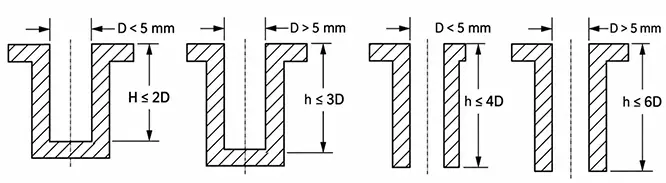
Holes are usually formed by core pins in the mold. The deeper and smaller the hole, the more likely the core pin is to deflect under injection pressure, so the depth-to-diameter ratio should be controlled.
Let the hole diameter be D. As an initial design reference:
Blind hole D < 5 mm: depth should generally not exceed about 2D
Blind hole D ≥ 5 mm: depth should generally be kept within about 3D
Through hole D < 5 mm: length can generally be kept within about 4D
Through hole D ≥ 5 mm: with good support at both ends of the core pin, the length may reach about 6D
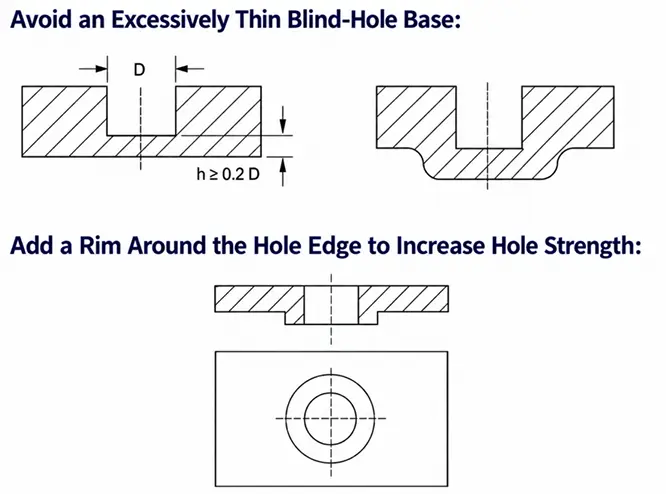
The bottom thickness of a blind hole should preferably be no less than about 0.2D
Hole location also requires attention:
Leave sufficient material between holes and between a hole and the part edge; as a general reference, use at least the larger of 2 times the wall thickness or 2 times the hole diameter;
- Keep holes away from major load-bearing areas whenever possible;
- Add a flange or boss around loaded holes to improve local strength;
- Align holes with the mold-opening direction whenever possible to avoid side holes that require slides.
7. Structural Strength Design
Improving part strength does not simply mean increasing wall thickness. In many cases, changing the structure is more effective than adding material.
Common approaches include:
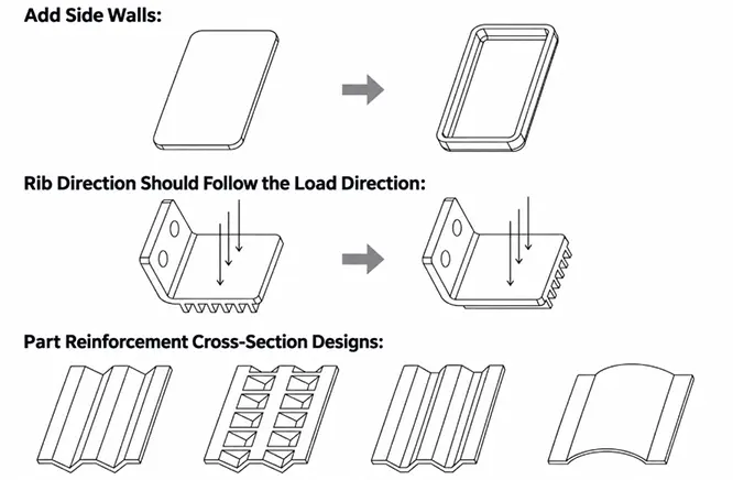
- Use ribs instead of increasing the overall wall thickness, and orient them according to the primary load direction;
- Use several properly sized ribs rather than one excessively thick or tall rib;
- Increase section stiffness with curved, flanged, channel-shaped, or box-shaped features;
- Add side walls to open sections to improve overall rigidity;
- Avoid sharp corners and abrupt section changes to reduce stress concentration.
If structural optimization is still insufficient to meet strength or stiffness requirements, glass-fiber-reinforced plastics can be considered.
8. Appearance Design
Appearance-related issues are best addressed during the design stage. Key considerations include:
Choose the right plastic material: For example, ABS is well suited to cosmetic parts and painted components, PC is commonly used when transparency or high impact strength is required, and PC/ABS is often chosen for housings that need both good appearance and toughness.
Avoid sink marks on cosmetic surfaces: Avoid placing overly thick bosses, ribs, or other material-heavy features directly behind visible surfaces.
Choose the gate location carefully: Keep gates away from primary cosmetic surfaces where possible, while also considering melt flow to reduce flow marks and local defects.
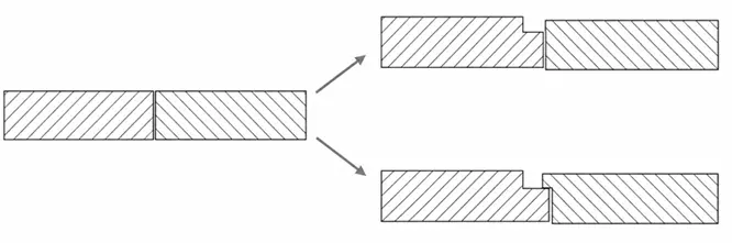
Use cosmetic grooves: Decorative grooves or separation lines can help visually disguise assembly edges, parting lines, and similar features.
Control weld lines: First optimize gate location and melt flow direction to minimize weld lines. If they cannot be avoided, texturing or painting can help reduce their visual impact.
9. Cost-Optimized Design
Reducing plastic part cost is not simply about choosing a cheaper material. The design itself should minimize material usage, part count, and mold complexity.
Design multifunctional parts: Where strength and assembly requirements allow, snap-fits can replace some screws or separate fasteners, reducing both part count and assembly operations.
Reduce material cost: Core out locally thick sections, or reduce wall thickness and add ribs to maintain stiffness while lowering material usage and cooling time.
Simplify part geometry: Minimize unnecessary undercuts, side holes, and complex features that would otherwise require slides, lifters, or other additional mold mechanisms.
Avoid overly tight tolerances: Only dimensions that directly affect assembly and function need tight control. Other dimensions should not be assigned unnecessarily strict tolerances.
10. Design for Injection Moldability
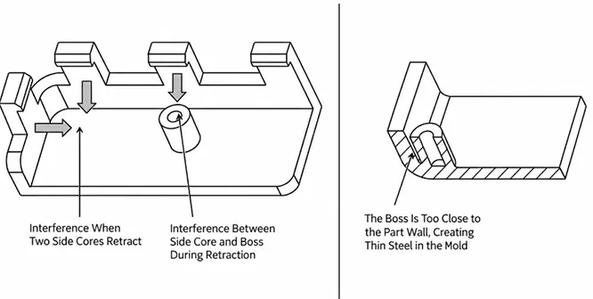
A feature that can be created in CAD is not necessarily easy to manufacture. For example, if snap-fits, undercuts, or similar features require lifters or slides, sufficient travel and clearance must be reserved for these mold mechanisms.
Another important issue is thin steel sections in the mold. When holes, narrow slots, deep ribs, or adjacent features are positioned too close together, only a very thin section of mold steel may remain between them. Such areas are difficult to machine and are more likely to deform or break during production.
11. Snap-Fit Design
A snap-fit must flex enough to engage during assembly without deforming so much that it breaks. Key design factors include:
Snap-fit length, thickness, width, engagement depth, root radius and stress concentration, as well as assembly clearance and actual deflection.
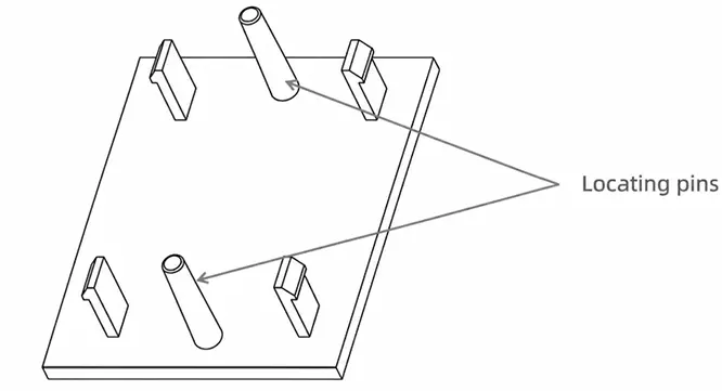
Do not rely entirely on snap-fits for positioning. Locating bosses, locating holes, or mating edges can be added so that the two parts are aligned first and then locked by the snap-fits. This improves assembly while reducing unnecessary lateral loads on the snap features.
For more details on snap-fit design, see: https://rjcmold.com/guides/snap-fit-design/
12. Fastener Assembly Design
First consider how many times the product will need to be assembled and disassembled. Plastic self-tapping screws can be used for assemblies that are permanent or rarely opened. If repeated servicing and disassembly are required, metal threaded inserts are generally more suitable.
When designing a boss, check the following:
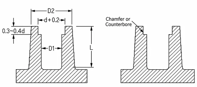
① The inner diameter should match the screw type and plastic material. If it is too small, the boss may split; if it is too large, thread engagement will be insufficient.
② The outer diameter must provide adequate hoop strength without creating an excessively thick section.
③ The boss hole should be at least about 0.5 mm deeper than the actual screw engagement depth to prevent the screw from bottoming out.
④ As an initial design reference, the effective thread engagement length should be at least about twice the nominal screw diameter.
⑤ A chamfer or countersink can be added at the top of the boss to guide the screw during insertion, improve assembly efficiency, and reduce damage around the hole entrance.
FAQ
Q1: Is mold flow analysis always necessary after a plastic part is designed?
Not always. Mold flow analysis is more valuable for large parts, thin-wall parts, complex flow paths, multi-gate designs, or components with strict warpage requirements.
Q2: Should logos and text on plastic parts be raised or recessed?
Either can work. The key is to avoid features that are too fine or too deep and to provide sufficient draft for proper release from the mold.
Q3: What additional considerations apply to transparent plastic parts?
Flow marks, weld lines, ejector-pin locations, and surface quality require tighter control. Wall-thickness variations that could cause optical distortion should also be minimized.
Q4: When should metal inserts be used?
Metal inserts are generally preferred when the joint requires higher tightening force, repeated assembly and disassembly, or better thread durability.
Q5: Can a 3D-printed prototype be used to directly verify the strength of an injection-molded part?
Not completely. 3D printing is useful for checking dimensions, assembly, and structural concepts, but its material properties, build orientation, and internal structure differ from those of the final injection-molded part.